415543 Night Stand PLEASE CONTACT US BEFORE RETURNING YOUR UNIT TO THE STORE 1-800-523-3987 www.sauder.com NOTE: THIS INSTRUCTION BOOKLET CONTAINS IMPORTANT SAFETY INFORMATION. PLEASE READ AND KEEP FOR FUTURE REFERENCE. English .................... Page 1-15 Français ...............Pages 16-18 Made in the USA Archbold, OH Espanol.............
TABLE OF CONTENTS ADULT ASSEMBLY REQUIRED Part Identification .......................3 Hardware Identification .............4 ASSEMBLY TOOLS REQUIRED Assembly Steps .................... 5-15 No. 2 Phillips Screwdriver Français .............................. 16-18 Tip Shown Actual Size Espanol............................... 19-21 Safety .......................................22 Hammer Warranty ...................................23 Scissors Page 2 www.sauder.
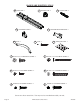
PART IDENTIFICATION: While not all parts are labeled, some of the parts will have a label or an inked letter on the edge to help distinguish similar parts from each other. Use this PART IDENTIFICATION to help identify similar parts. FF RIGHT END 1 KK BACK 1 GG LEFT END 1 NN DRAWER FRONT 1 HH TOP 1 D217 DRAWER SIDE 2 II BOTTOM 1 D218 DRAWER BACK 1 JJ SKIRT 1 D613 DRAWER BOTTOM 1 HH KK FF GG II JJ D217 D218 D613 D217 NN 415543 www.sauder.
HARDWARE IDENTIFICATION MM SLIDE SET -1 1F HIDDEN CAM - 4 5G ANGLE BRACKET - 3 30G DRAWER FRONT BRACKET -2 45K PULL - 1 1S 2F CAM DOWEL - 4 1N BLACK 9/16" LARGE HEAD SCREW - 8 35P APPLIQUE CARD - 1 NAIL - 8 2S BLACK 1-7/8" FLAT HEAD SCREW - 4 43S BLACK 1/2" FLAT HEAD SCREW - 4 49S BLACK 1-1/2” PAN HEAD SCREW - 4 52S SILVER 3/4" PAN HEAD SCREW - 4 53S SILVER 3/4” MACHINE SCREW - 2 Screws are shown actual size. You may receive extra hardware with your unit. Page 4 www.sauder.
S p te Look for this icon. It means a video assembly tip is available at: www.sauder.com/services/tips 1 Do not tighten the HIDDEN CAMS in this step. Arrow 1F (4 used) 2F GG FF Arrow Insert the metal end of the CAM DOWEL into the HIDDEN CAM. Assemble your unit on a carpeted floor or on the empty carton to avoid scratching your unit or the floor. Push four HIDDEN CAMS (1F) into the ENDS (FF and GG). Then, insert the metal end of a CAM DOWEL (2F) into each HIDDEN CAM. 415543 www.sauder.
S p te 2 DRAWER PIN (Save for Step 10) MM Using your Scissors, separate the SLIDES and the DRAWER PINS RIGHT SLIDE Notch Angled edge MM Finished edge Su H rfa ID ce D w EN it h C A M S LEFT SLIDE Straight edge MM Su H rfa ID ce D w EN it h C A M S FF GG 52S SILVER 3/4" PAN HEAD SCREW (4 used in this step) Finished edge NOTE: Before beginning this step, separate the SLIDES from the SLIDE SETS (MM) and the DRAWER PINS at the end of the SLIDES using a SCISSORS. Save the DRAWER PINS.
S p te 3 5G S ur fa ce w it h ho le s II JJ 5G 1S BLACK 9/16" LARGE HEAD SCREW (3 used in this step) Fasten three ANGLE BRACKETS (5G) to the BOTTOM (II) and SKIRT (JJ). Use three BLACK 9/16" LARGE HEAD SCREWS (1S). NOTE: Be sure the edges of the ANGLE BRACKETS are even with the edges of the BOTTOM (II) and SKIRT (JJ). 415543 www.sauder.
S p te 4 Finished edge s ole h ith Finished edge ew c a f ur S HH Sur f HIDace w DE ith NC AM S Sur f HIDace w DE ithou NC t AM S FF GG Fasten the TOP (HH) to the ENDS (FF and GG). Tighten four HIDDEN CAMS. Caution Risk of damage or injury. Hidden Cams must be completely tightened. Hidden Cams that are not completely tightened may loosen, and parts may separate. To completely tighten: Page 8 Start Arrow Tighten Maximum 210 degrees Arrow Minimum 190 degrees www.sauder.
S p te 5 1S BLACK 9/16" LARGE HEAD SCREW (3 used in this step) Edge with ANGLE BRACKET FF JJ GG II ith CKET w e fac RA Sur LE B G AN 2S BLACK 1-7/8" FLAT HEAD SCREW (4 used in this step) Fasten the BOTTOM (II) to the ENDS (FF and GG). Use four BLACK 1-7/8"FLAT HEAD SCREWS (2S). Fasten the SKIRT (JJ) to the BOTTOM (II) and ENDS (FF and GG). Use three BLACK 9/16" LARGE HEAD SCREWS (1S). 415543 www.sauder.
S Caution Do not stand the unit upright without the BACK fastened. The unit may collapse. p te 6 Edge without holes 1N NAIL (8 used in this step) KK GG HH FF Carefully turn the Night Stand over onto its front edges. Lay the BACK (KK) over the unit. Make equal margins along all three edges of the BACK (KK). Push on opposite corners of your unit if needed to make it “square”. Fasten the BACK (KK) to the unit using the NAILS (1N). Page 10 www.sauder.
S p te 7 Be sure the grooves in each part line up with each other on the inside of the drawer. D217 D218 D217 Groove 49S BLACK 1-1/2” PAN HEAD SCREW (4 used in this step) D218 D217 D217 D613 d he is in F e ac rf su Fasten the DRAWER SIDES (D217) to the DRAWER BACK (D218). Use four BLACK 1-1/2" PAN HEAD SCREWS (49S). Slide the DRAWER BOTTOM (D613) into the grooves in the DRAWER SIDES (D217) and DRAWER BACK (D218). 415543 www.sauder.
S p te 8 D217 D217 30G 43S 30G BLACK 1/2" FLAT HEAD SCREW (4 used this step) Fasten two DRAWER FRONT BRACKETS (30G) to the DRAWER SIDES (D217). Use four BLACK 1/2" FLAT HEAD SCREWS (43S). Page 12 www.sauder.
S p te 9 D217 D217 NN 45K 1S 53S BLACK 9/16" LARGE HEAD SCREW (2 used for the DRAWER FRONT BRACKETS) SILVER 3/4” MACHINE SCREW (2 used for the pull) Fasten the DRAWER FRONT (NN) to the DRAWER SIDES (D217). Use two BLACK 9/16" LARGE HEAD SCREWS (1S). Fasten the PULL (45K) to the DRAWER FRONT (NN). Use two SILVER 3/4" MACHINE SCREWS (53S). 415543 www.sauder.
S p te 10 DRAWER PIN D217 D217 Carefully stand the unit upright. To insert the drawer into the unit, line up the grooves on the DRAWER SIDES (D217) with the SLIDES in the unit. Slide the drawer into the unit until it is about 3" or 4" away from the back of the unit. Using your hammer, gently tap two DRAWER PINS (from Step 2) into the holes in the DRAWER SIDES (D217). NOTE: The DRAWER PINS are used as a locking system for the drawer.
S p te 11 25 lbs. 15 lbs. FF GG 25 lbs. 35P Peel the APPLIQUES from the APPLIQUE CARD (35P). Stick the APPLIQUES over the heads of each SCREW in the ENDS (FF and GG). NOTE: Please read the back pages of the instruction booklet for important safety information. This completes assembly. Clean with your favorite furniture polish or a damp cloth. Wipe dry. 415543 www.sauder.
415543 Utilisez les instructions d’assemblage en français avec les schémas étape par étape du manuel d’instruction en anglais. Chaque étape en français correspond à la même étape en anglais. La pièce devant être attachée à l’élément est représentée en gris sur les schémas de chaque étape pour plus de précision. Comparer la “Liste de pièces” ci-dessous avec la “PART IDENTIFICATION” du manuel en anglais pour vous familiariser avec les pièces avant l’assemblage.
ÉTAPE 1 ÉTAPE 5 Assembler l'élément sur un sol à moquette ou sur le carton vide pour éviter d'endommager l'élément ou le sol. Fixer le DESSOUS (II) aux EXTRÉMITÉS (FF et GG). Utiliser quatre VIS TÊTE PLATE 48 mm NOIRES (2S). Enfoncer quatre EXCENTRIQUES ESCAMOTABLES (1F) dans les EXTRÉMITÉS (FF et GG). Ensuite, insérer l'extrémité en métal de la CHEVILLE D'EXCENTRIQUE (2F) dans chaque EXCENTRIQUE ESCAMOTABLE. Fixer la PLINTHE (JJ) au DESSOUS (II) et aux EXTRÉMITÉS (FF et GG).
ÉTAPE 10 ÉTAPE 11 Avec précaution, placer l'élément dans sa position verticale. Décoller les APPLIQUÉS de la FICHE D'APPLIQUÉS (35P). Centrer les APPLIQUÉS sur la tête de la chaque VIS visible dans les EXTRÉMITÉS (FF et GG). Pour insérer le tiroir dans l'unité, aligner les rainures des CÔTÉS DE TIROIR (D217) avec les COULISSES de l'unité. Faire glisser le tiroir dans l’unité jusqu’à ce qu’il se trouve à environ 7,6 cm ou 10 cm de l’arrière de l’unité.
415543 Use estas instrucciones de ensamblaje en español junto con las figuras paso-a-paso provistas en el folleto inglés. Cada paso en español corresponde al mismo paso en inglés. Se destacan las figuras de cada paso con una tonalidad oscura para mostrar precisamente cual parte se debe montar a la unidad. Compare la “Lista de Part” abajo con la “Part Identification” en el folleto en inglés para familiarizarse con Las partes de ensamblaje.
PASO 1 PASO 5 Ensamble la unidad sobre un piso alfombrado o sobre el cartón vacío para evitar rayar la unidad o el piso. Fije el FONDO (II) a los EXTREMOS (FF y GG). Utilice cuatro TORNILLOS NEGROS DE CABEZA PERDIDA de 48 mm (2S). Empuje cuatro EXCÉNTRICOS ESCONDIDOS (1F) dentro de los EXTREMOS (FF y GG). A continuación, inserte el extremo de metal de un PASADOR DE EXCÉNTRICO (2F) dentro de cada EXCÉNTRICO ESCONDIDO. Fije el FALDÓN (JJ) al FONDO (II) y a los EXTREMOS (FF y GG).
PASO 10 PASO 11 Cuidadosamente ponga la unidad en posición vertical. Separe las APLICACIONES de la TARJETA CON APLICACIONES (35P). Centre las APLICACIONES sobre la cabeza de cada TORNILLO visible dentro de los EXTREMOS (FF y GG). Para insertar el cajón dentro de la unidad, alinee las ranuras en los LADOS DE CAJÓN (D217) con las CORREDERAS de la unidad. Deslice el cajón en la unidad hasta que se halle aproximadamente a 7.6 cm o 10 cm de la parte posterior de su unidad.
WARNING Please use your furniture correctly and safely. Improper use can cause safety hazards, or damage to your furniture or household items. Carefully read the following chart. Look out for: What can happen: How to avoid the problem: • Overloaded drawers and shelves. • Risk of injury. • Top-heavy furniture can tip over. • Overloaded drawers or shelves can break. • Never exceed the weight limits shown in the instructions. • Work from bottom to top when loading shelves and drawers.
1-YEAR LIMITED WARRANTY 1. Sauder Woodworking Co. (Sauder®) provides limited warranty coverage to the original purchaser of this product for a period of one year from the date of purchase against defects in materials or workmanship of Sauder furniture components. As used in this Warranty, “defect” means imperfections in components which substantially impair the utility of the product. This Warranty gives you specific legal rights, and you may also have other rights which vary from state to state. 2.
Dear valued customer: Thank you for your purchase from the Sauder family companies. It’s our pleasure to provide you with an affordable solution that meets your furniture and storage needs. I hope you will enjoy it for years to come. I am pleased with this company’s consistent ability to amaze the customer over time. My grandfather, Erie Sauder, founded the company in 1934 and later invented and patented the first commercially successful ready-to-assemble table.