sauder.com WARNING CHOKING HAZARD - Small Parts Not for children under 3 years. Adult assembly required. 4-Drawer Chest Pogo Collection | 416532 NOTE: THIS INSTRUCTION BOOKLET CONTAINS IMPORTANT SAFETY INFORMATION. Need help? Visit Sauder.com to view video assembly tips or chat with a live rep. Prefer the phone? Call 1-800-523-3987. Share your journey! PLEASE READ AND KEEP FOR FUTURE REFERENCE.
Table of Contents Part Identification 2-3 Hardware Identification Assembly Steps Assembly Tools Required No. 2 Phillips Screwdriver Tip Shown Actual Size 4 5-18 Hammer Français 19-21 Español 22-24 Safety 25-26 Warranty Not actual size Skip the power trip. This time. 27 Part Identification å While not all parts are labeled, some of the parts will have a label or an inked letter on the edge to help distinguish similar parts from each other.
Now you know our ABCs. Part Identification C M29 H A E B D D I D22 D80 D704 D23 www.sauder.
Hardware Identification å Screws are shown actual size. You may receive extra hardware with your unit. 35GA CABINET RIGHT - 4 10A SLIDE CAM - 8 4G METAL BRACKET - 2 1F 35GC DRAWER RIGHT - 4 35GB CABINET LEFT - 4 HIDDEN CAM - 14 59K KNOB - 8 2F 27F CAM DOWEL - 14 5L WARNING LABEL - 1 1N 35GD DRAWER LEFT - 4 HIDDEN CONNECTOR - 2 1G SAFETY BRACKET - 1 NAIL - 22 1R METAL PIN - 2 WARNING Serious or fatal crushing injuries can occur from furniture tip-over.
Look for this icon. It means a video assembly tip is available at www.sauder.com/services/tips Step 1 å Insert a CONNECTOR SCREW (8S) into each HIDDEN CONNECTOR (27F). 27F 8S Step 2 å Assemble your unit on a carpeted floor or on the empty carton to avoid scratching your unit or the floor. å Use your hammer to tap two HIDDEN CONNECTORS (27F) with SCREWS into the ENDS (A and B). 27F 27F A B www.sauder.
Step 3 å Push fourteen HIDDEN CAMS (1F) into the ENDS (A and B), BOTTOMS (D), SMALL BACK (E), and DRAWER BRACES (J). Then, insert the metal end of a CAM DOWEL (2F) into each HIDDEN CAM. Do not tighten the HIDDEN CAMS in this step. Arrow 2F 1F (14 used) E A B D Arrow D J J J J Insert the metal end of the CAM DOWEL into the HIDDEN CAM. Arrow 1F 2F Page 6 416532 www.sauder.
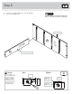
Step 4 å Fasten the CABINET RIGHTS (35GA) to the RIGHT END (A) and the CABINET LEFTS (35GB) to the LEFT END (B). Use sixteen GOLD 5/16" FLAT HEAD SCREWS (3S) through holes #1 and #3. Remember: Righty tighty. Lefty loosey. 3S GOLD 5/16" FLAT HEAD SCREW (16 used in this step) Finished edge Roller end 1 2 1 3 2 1 3 2 3 1 3 2 2 3 1 A 3 3 1 2 1 3 S HI urfa DD ce EN wi CA th M S 2 2 B S HI urfa DD ce EN wi CA th M S 1 Roller end Finished edge www.sauder.
Step 5 å Fasten one of the BOTTOMS (D) to the LEFT END (B). Tighten the HIDDEN CAM. Caution Do not stand the unit upright without the BACKS fastened. The unit may collapse. Finished edge B ut itho S w e fac AM Sur DEN C HID D Caution Risk of damage or injury. HIDDEN CAMS must be completely tightened. HIDDEN CAMS that are not completely tightened may loosen, and parts may separate. To completely tighten: Page 8 Sur withface HID CA DEN MS This hole must be here.
Step 6 å Fasten a METAL BRACKET (4G) to the BOTTOM (D). Use a BLACK 9/16" LARGE HEAD SCREW (1S). å å Insert two METAL PINS (1R) into the ends of the SMALL BACK (E). å å NOTE: You will not tighten the HIDDEN CAM in this step. Insert the METAL PIN and CAM DOWEL in one end of the SMALL BACK (E) into the LEFT END (B). Fasten the SMALL BACK (E) to the BOTTOM (D). Use a BLACK 9/16" LARGE HEAD SCREW (1S) through the METAL BRACKET and into the SMALL BACK.
Step 7 å Fasten the other BOTTOM (D) to the LEFT END (B). Tighten the HIDDEN CAM. å Fasten the RIGHT END (A) to the BOTTOMS (D). Tighten two HIDDEN CAMS. å NOTE: Be sure the METAL PIN and CAM DOWEL in the SMALL BACK (E) insert into the RIGHT END. You will not tighten the HIDDEN CAM in the SMALL BACK in this step. This hole must be here.
Step 8 å Fasten the TOP (C) to the ENDS (A and B) Tighten four HIDDEN CAMS. å Fasten the TOP MOLDING (M29) to the TOP (C). Use three BROWN 1-1/2" FLAT HEAD SCREWS (14S). 14S BROWN 1-1/2" FLAT HEAD SCREW (3 used in this step) Curved edge B Curved edge Unfi ce urfa s ed nish M29 A e fac Sur s ole h t ou with C Maximum 210 degrees Arrow Minimum 190 degrees www.sauder.
Step 9 å Fasten a METAL BRACKET (4G) to the BOTTOM (D). Use a BLACK 9/16" LARGE HEAD SCREW (1S). å NOTE: The METAL BRACKET should be even with the edge of the BOTTOM. å Fasten the BASE (I) to the ENDS (A and B) and BOTTOM (D). Tighten two HIDDEN CONNECTORS and use a BLACK 9/16" LARGE HEAD SCREW (1S) through the METAL BRACKET and into the BASE. Don't worry. It isn't Rome. This can be built in a day.
Step 10 å Carefully turn your unit over onto its front edges and tighten the two HIDDEN CAMS in the SMALL BACK (E). å å Unfold the LARGE BACK (H) and lay it over your unit. å Fasten the bottom edge of the LARGE BACK (H) to your unit. Use eight BLACK 9/16" LARGE HEAD SCREWS (1S) into the pre-drilled holes in the SMALL BACK (E). å Fasten the sides and top edges of the LARGE BACK (H) to your unit. Use the NAILS (1N). Caution Do not stand the unit upright without the BACKS fastened.
Step 11 VIEW THE T-LOCK BOX VIDEO The tabs should insert freely into the slots. Gently tilt the DRAWER SIDES side to side until the tabs slip into the slots. 1 With the palm of your hand, tap the DRAWER BOTTOM down into the groove. 2 Un fi su nish rfa ed ce D22 D704 D22 F D23 F D23 Groove Be sure the DRAWER BOTTOM inserts into the DRAWER FRONT groove. Insert the DRAWER SIDES (D22 and D23) at an angle into the slot at each end of the DRAWER FRONT (F).
Step 12 å å Insert a SLIDE CAM (10A) into the DRAWER SIDES (D22 and D23). å NOTE: The screw head in the CAM must be visible through the slotted hole in the SLIDE. å Repeat this step for the other drawers. Fasten a DRAWER RIGHT (35GC) to the RIGHT DRAWER SIDE (D22) and a DRAWER LEFT (35GD) to the LEFT DRAWER SIDE (D23). Use four GOLD 5/16" FLAT HEAD SCREWS (3S) through holes #1 and #3.
Step 13 å Fasten two KNOBS (59K) to the DRAWER FRONT (F). Use two BLACK 1-1/8" PAN HEAD SCREWS (9S). å Repeat this step for the other drawers. 9S BLACK 1-1/8" PAN HEAD SCREW (8 used in this step) F 59K 59K Page 16 416532 www.sauder.
Step 14 å å Carefully stand your unit upright. å To insert the drawers into your unit, tip the front of the drawers down and drop the rollers on the drawers behind the rollers on the unit. Lift the front of the drawers up and slide them into the unit. å Apply the WARNING LABEL (5L) to the upper DRAWER BOTTOM (D704). You should be able to read the label when the drawer is open. When the drawer is closed, it will hide the label. Peel off the backing and apply the label as shown in the diagram.
Step 15 å To make adjustments to the drawers, loosen SCREW #3 in the SLIDES a 1/4 turn, then turn the CAM clockwise or counter-clockwise. Notice how the drawer raises or lowers as you turn the CAM. The higher the screw in the oblong hole, the higher your drawer front will be. The lower the screw, the lower the drawer front. By adjusting the drawers this way, it will help the DRAWER FRONTS line up better when closed. Tighten the SCREW when finished with adjustments.
416532 Utilisez les instructions d’assemblage en français avec les schémas étape par étape du manuel d’instruction en anglais. Chaque étape en français correspond à la même étape en anglais. La pièce devant être attachée à l’élément est représentée en gris sur les schémas de chaque étape pour plus de précision. Comparer la “Liste de pièces” ci-dessous avec la “PART IDENTIFICATION” du manuel en anglais pour vous familiariser avec les pièces avant l’assemblage.
ÉTAPE 1 ÉTAPE 6 Insérer une VIS DE CONNECTEUR (8S) dans chaque CONNECTEUR ESCAMOTABLE (27F). Fixer une CONSOLE EN MÉTAL (4G) au DESSOUS (D). Utiliser une VIS TÊTE LARGE 14 mm NOIRE (1S). ÉTAPE 2 Insérer deux GOUPILLES EN MÉTAL (1R) dans l’extrémité du PETIT ARRIÈRE (E). Assembler l'élément sur un sol à moquette ou sur le carton vide pour éviter d'endommager l'élément ou le sol.
ÉTAPE 10 ÉTAPE 13 Attention: Ne pas relever l'élément dans sa position verticale avant d'avoir fixé les ARRIÈRES. L'élément risque de s'effondrer. Fixer deux BOUTONS (59K) au DEVANT DE TIROIR (F). Utiliser deux VIS TÊTE GOUTTE DE SUIF 28 mm NOIRES (9S). Avec précaution, retourner l'élément sur ses chants avant pour serrer les deux EXCENTRIQUES ESCAMOTABLES situées sur le PETIT ARRIÈRE (E). Répéter cette étape pour les autres tiroirs. Déplier le GRAND ARRIÈRE (H) et le placer sur l'élément.
416532 Use estas instrucciones de ensamblaje en español junto con las figuras paso-a-paso provistas en el folleto inglés. Cada paso en español corresponde al mismo paso en inglés. Se destacan las figuras de cada paso con una tonalidad oscura para mostrar precisamente cual parte se debe montar a la unidad. Compare la “Lista de Part” abajo con la “Part Identification” en el folleto en inglés para familiarizarse con Las partes de ensamblaje.
PASO 1 PASO 6 Inserte un TORNILLO CONECTOR (8S) dentro de cada CONECTOR INVISIBLE (27F). Fije un SOPORTE DE METAL (4G) al FONDO (D). Utilice un TORNILLO NEGRO DE CABEZA GRANDE de 14 mm (1S). PASO 2 Ensamble la unidad sobre un piso alfombrado o sobre el cartón vacío para evitar rayar la unidad o el piso. Utilice un martillo para ligeramente clave dos CONECTORES INVISIBLES (27F) con TORNILLOS dentro de los EXTREMOS (A y B). PASO 3 Inserte dos ESPIGAS DE METAL (1R) en los extremos del DORSO PEQUEÑO (E).
PASO 10 PASO 13 Precaución: No coloque la unidad en posición vertical hasta que se fije los DORSOS. La unidad podría caerse. Fije dos POMOS (59K) a la CARA DE CAJÓN (F). Utilice dos TORNILLOS NEGROS DE CABEZA REDONDA de 28 mm (9S). Cuidadosamente vuelva la unidad para que repose sobre los bordes delanteros para apretar los dos EXCÉNTRICOS ESCONDIDOS sujetados al DORSO PEQUEÑO (E). Repita este paso para los otros cajones. Desdoble el DORSO GRANDE (H) y colóquelo sobre la unidad.
WARNING Please use your furniture correctly and safely. Improper use can cause safety hazards, or damage to your furniture or household items. Carefully read the following chart. Look out for: What can happen: How to avoid the problem: • Overloaded dresser drawers and shelves. • Risk of injury. • Top-heavy furniture can tip over. • Overloaded drawers and shelves can break. • Never exceed the weight limits shown in the instructions. • Work from bottom to top when loading shelves and drawers.
ADVERTENCIA Por favor use el mobiliario correcta y seguramente. El mal uso puede causar riesgos de seguridad o daño a las unidades o artículos domésticos. Cuidadosamente lea la tabla a continuación. Esté alerto de: Puede ocurrir: Evitar el problema: • Cajones y estantes sobrecargados. • Un riesgo de lesiones. • El mobiliario inestable puede volcarse. • Los cajones o estantes sobrecargados pueden romperse. • Nunca exceder los límites de peso indicados en las instrucciones.
5-YEAR LIMITED WARRANTY 1. Sauder Woodworking Co. (Sauder®) provides limited warranty coverage to the original purchaser of this product for a period of five years from the date of purchase against defects in materials or workmanship of Sauder furniture components. As used in this Warranty, “defect” means imperfections in components which substantially impair the utility of the product. This Warranty gives you specific legal rights, and you may also have other rights which vary from state to state. 2.
Dear Valued Customer: So, how did it go? Thanks so much for choosing Sauder® furniture. I hope the purchase and assembly process was a positive experience and you feel good about the furniture you just built. If you need assistance or want to learn more, please contact our award-winning, Ohio-based customer service team at 800-523-3987 or Sauder.com. Set a world record for speed? Feeling good about yourself? Nice. Get social with it on any of these quality share sites.