sauder.com Don't get caught with your pants on the ground. 4-Drawer Chest Dakota Pass Collection | 418175 NOTE: THIS INSTRUCTION BOOKLET CONTAINS IMPORTANT SAFETY INFORMATION. Need help? Visit Sauder.com to view video assembly tips or chat with a live rep. Prefer the phone? Call 1-800-523-3987. Share your journey! PLEASE READ AND KEEP FOR FUTURE REFERENCE.
Table of Contents Part Identification Assembly Tools Required 2-3 Hardware Identification No. 2 Phillips Screwdriver Tip Shown Actual Size 4 Assembly Steps 5-18 Hammer Français 19-21 Español 22-24 Safety 25-26 Warranty Not actual size Skip the power trip. This time. 27 Now you know our ABCs. Part Identification å While not all parts are labeled, some of the parts will have a label or an inked letter on the edge to help distinguish similar parts from each other.
Part Identification C E H A H J F B D K G D30 D175 D982 D31 M I L www.sauder.
Hardware Identification å Screws are shown actual size. You may receive extra hardware with your unit. 35AA UNIVERSAL CABINET RAIL - 8 8F 35AC DRAWER RIGHT - 4 35AD DRAWER LEFT - 4 CAM SCREW - 15 10F TWIST-LOCK® FASTENER - 8 15F WOOD DOWEL - 2 5L WARNING LABEL - 1 13M WASHER - 1 60M SAFETY STRAP - 1 61M 17F 1F MOLDING CONNECTOR - 2 SAFETY DRYWALL 1N ANCHOR - 1 HIDDEN CAM - 15 28K KNOB- 8 NAIL - 30 WARNING Serious or fatal crushing injuries can occur from furniture tip-over.
Look for this icon. It means a video assembly tip is available at www.sauder.com/services/tips Step 1 å Assemble your unit on a carpeted floor or on the empty carton to avoid scratching your unit or the floor. å To begin assembly, push a SAUDER TWIST-LOCK® FASTENER (10F) into the large holes in the ENDS (A and B) and BOTTOM (D). Do not tighten the TWIST-LOCK® FASTENERS in this step. 10F B A D 10F www.sauder.
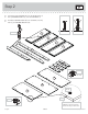
Step 2 å Turn fifteen CAM SCREWS (8F) into the FRONT LEGS (F and G), DRAWER FRONTS (I), and TOP MOLDING (J). å Push fifteen HIDDEN CAMS (1F) into the ENDS (A and B), TOP (C), and DRAWER BRACES (M). 8F (15 used) I I I I G F J M M M M Arrow 1F (15 used) B A Arrow C Hole Arrow 1F Page 6 The arrow in the HIDDEN CAM must point toward the hole in the edge of the board. 418175 www.sauder.
Step 3 å å Fasten the UNIVERSAL CABINET RAILS* (35AA) to the ENDS (A and B). Use sixteen GOLD 5/16" FLAT HEAD SCREWS (3S) through holes #1 and #3. Remember: Righty tighty. Lefty loosey. *patent pending glide system Edge with HIDDEN CAMS Glide end 1 2 1 3 2 1 3 2 1 3 3 2 A 2 3 1 3 S HI urfa DD ce EN wi CA th M S 2 3 1 2 3 1 B 2 S HI urfa DD ce EN wi CA th M S 1 Glide end 3S Edge with HIDDEN CAMS www.sauder.
Step 4 å Fasten the REAR LEGS (H) to the ENDS (A and B). Use eight BLACK 2-1/4" FLAT HEAD SCREWS (26S). These surfaces should be even. Edge with HIDDEN CAMS These surfaces should be even. H S HI urfa DD ce EN wi CA th M S A H S HI urfa DD ce EN wi CA th M S B Angled edge Edge with HIDDEN CAMS 26S BLACK 2-1/4" FLAT HEAD SCREW (8 used in this step) Page 8 418175 www.sauder.
Step 5 å Fasten the LEFT END (B) to the TOP (C). Tighten two TWIST-LOCK® FASTENERS. å Fasten the BOTTOM (D) to the LEFT END (B). Tighten two TWIST-LOCK® FASTENERS. Caution Do not stand the unit upright without the BACK fastened. The unit may collapse. How to use the SAUDER TWIST-LOCK® FASTENER 1. Insert the dowel end of the FASTENER into the hole of the adjoining part. NOTE: The dowel end of the FASTENER must remain fully inserted in the hole of the adjoining part while locking the FASTENER. 2.
Step 6 å Slide the BOTTOM MOLDING* (K) onto the notched edge of the BOTTOM (D). å Fasten the RIGHT END (A) to the TOP (C) and BOTTOM (D). Tighten four TWIST-LOCK® FASTENERS. å *U.S. Patent No. 5,499,886 Notched edge Edge with HIDDEN CAMS C K D A ut itho S w e fac AM Sur DEN C HID Slide the BOTTOM MOLDING (K) onto the notched edge. Page 10 H 418175 www.sauder.
Step 7 å Tap two MOLDING CONNECTORS (17F) into the notches in the FRONT LEGS (F and G) and TOP MOLDING (J). Don't worry. It isn't Rome. This can be built in a day. Use your hammer to tap the MOLDING CONNECTORS (17F) into the notches in the FRONT LEGS and MOLDING. Flat end Flat end 17F 17F G F J www.sauder.
Step 8 å Insert two WOOD DOWELS (15F) into the FRONT LEGS (F and G). å NOTE: You may need someone's help with carefully flipping the FRONT LEGS and TOP MOLDING over. å Fasten the FRONT LEGS (F and G) and TOP MOLDING (J) to the ENDS (A and B) and TOP (C). Tighten eleven HIDDEN CAMS. å 1 2 NOTE: Be sure the WOOD DOWELS in the FRONT LEGS insert into the holes in the ENDS. J G C B F A 15F Page 12 418175 www.sauder.
Step 9 å Carefully turn your unit over onto its front edges. Unfold the BACK (E) and lay it over your unit. å Line up the large holes in the BACK (E) over the heads of the SCREWS in the REAR LEGS (H). This will help center your BACK. Make equal margins along all four edges of the BACK. Push on opposite corners of your unit if needed to make it "square". å å Caution Do not stand the unit upright without the BACK fastened. The unit may collapse.
Step 10 VIEW THE T-LOCK BOX VIDEO The tabs should insert freely into the slots. Gently tilt the DRAWER SIDES side to side until the tabs slip into the slots. 1 2 With the palm of your hand, tap the DRAWER BOTTOM down into the groove. Un fi su nish rfa ed ce D30 D982 D30 I D31 I Groove å D31 Be sure the DRAWER BOTTOM inserts into the DRAWER FRONT groove. Insert the DRAWER SIDES (D30 and D31) at an angle into the slot at each end of the DRAWER FRONT (I).
Step 11 å Fasten a DRAWER RIGHT (35AC) to the DRAWER RIGHT SIDE (D30) and a DRAWER LEFT (35AD) to the DRAWER LEFT SIDE (D31). Use four GOLD 5/16" FLAT HEAD SCREWS (3S) through holes #1 and #2. å NOTE: The parts are marked "DRAWER RIGHT" and "DRAWER LEFT" for easy identification. å å NOTE: The glides are not intended to rotate. Repeat this step for the other drawers. Glide end 1 2 D31 Glide end D30 1 2 3S GOLD 5/16" FLAT HEAD SCREW (16 used in this step) www.sauder.
Step 12 å Fasten the DRAWER FRONT MOLDING (L) to the DRAWER FRONT (I). Use three BLACK 1" PAN HEAD SCREWS (60S). å Fasten two KNOBS (28K) to the DRAWER FRONT MOLDING (L). Use two SILVER 1-1/2" MACHINE SCREWS (95S) through the DRAWER FRONT (I), through the DRAWER FRONT MOLDING, and into the KNOBS. å Repeat this step for the other drawers. Almost time to celebrate! With a nap.
Step 13 å å å Carefully stand your unit upright. å INSTALLATION INSTRUCTIONS: (Also available at www.yl-anchors.com) 1. Insert the SAFETY DRYWALL ANCHOR (61M) through the WASHER (13M) and one end of the SAFETY STRAP (60M). 2. Using a Phillips screwdriver or a hand drill, press screw slightly onto the drywall. 3. Apply pressure; turn the screw until a pilot hole is made and the nylon sheath slips through. 4. Turn the screw until it is flush against the wall and you feel a firm resistance. 5.
Step 14 å To insert the drawers into your unit, tip the front of the drawer down and drop the glides on the drawer behind the glides on the unit. Lift the front of the drawer up and slide it into the unit. å Apply the WARNING LABEL (5L) to the upper DRAWER BOTTOM (D982). You should be able to read the label when the drawer is open. When the drawer is closed, it will hide the label. Peel off the backing and apply the label as shown in the diagram.
418175 Utilisez les instructions d’assemblage en français avec les schémas étape par étape du manuel d’instruction en anglais. Chaque étape en français correspond à la même étape en anglais. La pièce devant être attachée à l’élément est représentée en gris sur les schémas de chaque étape pour plus de précision. Comparer la “Liste de pièces” ci-dessous avec la “PART IDENTIFICATION” du manuel en anglais pour vous familiariser avec les pièces avant l’assemblage.
ÉTAPE 1 ÉTAPE 6 Ne pas serrer les FIXATIONS TWIST-LOCK® à cette étape. Enfiler la MOULURE DE DESSOUS* (K) sur le chant cranté du DESSOUS (D). Assembler l'élément sur un sol à moquette ou sur le carton vide pour éviter d'endommager l'élément ou le sol. Pour commencer l'assemblage, enfoncer une FIXATION TWIST-LOCK® SAUDER (10F) dans les gros trous des EXTRÉMITÉS (A et B) et le DESSOUS (D).
ÉTAPE 10 ÉTAPE 13 1 Insérer les CÔTÉS DE TIROIR (D30 et D31) en biseau dans la fente dans chaque extrémité du DEVANT DE TIROIR (I). Relever, avec précaution, l'élément dans sa position verticale. 2 Enfiler le FOND DE TIROIR (D982) dans les rainures des CÔTÉS DE TIROIR (D30 et D31) et du DEVANT DE TIROIR (I). 3 Fixer l’ENTRETOISE DE TIROIR (M) au DEVANT DE TIROIR (I). Serrer un EXCENTRIQUE ESCAMOTABLE. 4 Fixer l'ARRIÈRE DE TIROIR (D175) aux CÔTÉS DE TIROIR (D30 et D31) et à l’ENTRETOISE DE TIROIR (M).
418175 Use estas instrucciones de ensamblaje en español junto con las figuras paso-a-paso provistas en el folleto inglés. Cada paso en español corresponde al mismo paso en inglés. Se destacan las figuras de cada paso con una tonalidad oscura para mostrar precisamente cual parte se debe montar a la unidad. Compare la “Lista de Part” abajo con la “Part Identification” en el folleto en inglés para familiarizarse con Las partes de ensamblaje.
PASO 1 PASO 6 No apriete los SUJETADORES TWIST-LOCK® en este paso. Deslice la MOLDURA DE FONDO* (K) sobre el borde con muesca del FONDO (D). Ensamble la unidad sobre un piso alfombrado o sobre el cartón vacío para evitar rayar la unidad o el piso. Para comenzar el ensamblaje, empuje un SUJETADOR TWIST-LOCK® SAUDER (10F) dentro de los agujeros grandes de los EXTREMOS (A y B) y del FONDO (D).
PASO 10 PASO 13 1 Inserte los LADOS DE CAJÓN (D30 y D31) en ángulo en el encaje en cada extremo de la CARA DE CAJÓN (I). Cuidadosamente ponga la unidad en posición vertical. 2 Deslice el FONDO DE CAJÓN (D982) en las ranuras de los LADOS DE CAJÓN (D30 y D31) y de la CARA DE CAJÓN (I). 3 Fije la RIOSTRA DE CAJÓN (M) a la CARA DE CAJÓN (I). Apriete un EXCÉNTRICO ESCONDIDO. 4 Fije el DORSO DE CAJÓN (D175) a los LADOS DE CAJÓN (D30 y D31) y a la RIOSTRA DE CAJÓN (M).
WARNING Please use your furniture correctly and safely. Improper use can cause safety hazards, or damage to your furniture or household items. Carefully read the following chart. Look out for: What can happen: How to avoid the problem: • Overloaded dresser drawers and shelves. • Risk of injury. • Top-heavy furniture can tip over. • Overloaded drawers and shelves can break. • Never exceed the weight limits shown in the instructions. • Work from bottom to top when loading shelves and drawers.
ADVERTENCIA Por favor use el mobiliario correcta y seguramente. El mal uso puede causar riesgos de seguridad o daño a las unidades o artículos domésticos. Cuidadosamente lea la tabla a continuación. Esté alerto de: Puede ocurrir: Evitar el problema: • Cajones y estantes de cómoda sobrecargados. • Un riesgo de lesiones. • El mobiliario inestable puede volcarse. • Los cajones o estantes sobrecargados pueden romperse. • Nunca exceder los límites de peso indicados en las instrucciones.
5-YEAR LIMITED WARRANTY 1. Sauder Woodworking Co. (Sauder®) provides limited warranty coverage to the original purchaser of this product for a period of five years from the date of purchase against defects in materials or workmanship of Sauder furniture components. As used in this Warranty, “defect” means imperfections in components which substantially impair the utility of the product. This Warranty gives you specific legal rights, and you may also have other rights which vary from state to state. 2.
Dear Valued Customer: So, how did it go? Thanks so much for choosing Sauder® furniture. I hope the purchase and assembly process was a positive experience and you feel good about the furniture you just built. If you need assistance or want to learn more, please contact our award-winning, Ohio-based customer service team at 800-523-3987 or Sauder.com. Set a world record for speed? Feeling good about yourself? Nice. Get social with it on any of these quality share sites.