sauder.com Sit and surf. Computer Desk Cannery Bridge Collection | 419352 NOTE: THIS INSTRUCTION BOOKLET CONTAINS IMPORTANT SAFETY INFORMATION. Need help? Visit Sauder.com to view video assembly tips or chat with a live rep. Prefer the phone? Call 1-800-523-3987. Share your journey! PLEASE READ AND KEEP FOR FUTURE REFERENCE. English pg 1-31 Français pg 32-35 Español pg 36-40 Lot # 385176 01/21/16 Purchased: __________________ Be sure to give us a ring before making any returns.
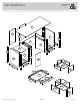
Table of Contents Part Identification Hardware Identification Assembly Steps Assembly Tools Required 2-3 No. 2 Phillips Screwdriver Tip Shown Actual Size 4-5 6-31 Hammer Français 32-35 Español 36-40 Safety Not actual size Skip the power trip. This time. 41-42 Warranty 43 Part Identification å While not all parts are labeled, some of the parts will have a label or an inked letter on the edge to help distinguish similar parts from each other.
Now you know our ABCs. Part Identification E M H H A S L G S R C F K Q M L D L B J D150 F Q R D26 D702 L D27 N D266 D468 B27 D469 D267 P EE D151 D28 D954 D29 O www.sauder.
Hardware Identification å Screws are shown actual size. You may receive extra hardware with your unit.
Hardware Identification å Screws are shown actual size. You may receive extra hardware with your unit. 2S BLACK 1-7/8" FLAT HEAD SCREW - 4 3S 9S BLACK 1-1/8" PAN HEAD SCREW - 4 11S BLACK 1/2" FLAT HEAD SCREW - 4 GOLD 5/16" FLAT HEAD SCREW - 24 15S SILVER 5/8" MACHINE SCREW - 6 17S BLACK 7/8" LARGE HEAD SCREW - 2 30S BLACK 1-9/16" FLAT HEAD SCREW - 14 32S BLACK 9/16" FLAT HEAD SCREW - 4 100S BLACK 2-3/4" FLAT HEAD SCREW - 6 www.sauder.
Look for this icon. It means a video assembly tip is available at www.sauder.com/services/tips Step 1 å Assemble your unit on a carpeted floor or on the empty carton to avoid scratching your unit or the floor. å Push thirty HIDDEN CAMS (1F) into the ENDS (A and B), UPRIGHTS (C and D), BOTTOMS (F), and MODESTY PANEL (G). Then, insert the metal end of eighteen CAM DOWELS (2F) into each HIDDEN CAM, except the long edges of the ENDS (A and B) and UPRIGHTS (C and D).
Step 2 å å å å Turn twelve CAM SCREWS (8F) into the FRONT LEGS (L). Remember: Righty tighty. Lefty loosey. NOTE: Position the LEGS exactly as shown. NOTE: Use the exact holes shown. Insert four WOOD DOWELS (15F) into the holes in the FRONT LEGS (L). 8F (12 used) 3 used in each leg These holes are closer to these edges. 15F L L L These holes are closer to these edges. www.sauder.
Step 3 å Fasten the ENDS (A and B) and UPRIGHTS (C and D) to the FRONT LEGS (L). Tighten twelve HIDDEN CAMS. å NOTE: Be sure the WOOD DOWELS in the FRONT LEGS insert into the holes in the ENDS and UPRIGHTS. 1 These surfaces should be even. 2 These ends should be even. These surfaces should be even. L A S HI urfa DD ce EN wi CA th M S These ends should be even. View after the LEG is fastened S HI urfa DD ce EN wi CA th M S B These surfaces should be even. L These ends should be even.
Step 4 å å Flip the ENDS (A and B) over. å Slide the END MOLDINGS (R) onto the ENDS (A and B). Line up the grooves in the MOLDINGS over the heads of the SCREWS in the ENDS. Turn four BLACK 9/16" FLAT HEAD SCREWS (32S) into the ENDS (A and B) until the shoulders of the SCREWS rest on the surfaces of the ENDS. These edges should be even. S HI urfa DD ce EN wi CA tho M ut S R A S HI urfa DD ce EN wi CA tho M ut S B These edges should be even.
Step 5 å Fasten the BACK LEGS (M) to the ENDS (A and B). Use six BLACK 2-3/4" FLAT HEAD SCREWS (100S). These ends should be even. M A B M View after the LEG is fastened 100S BLACK 2-3/4" FLAT HEAD SCREW (6 used in this step) Page 10 419352 www.sauder.
Step 6 å å Flip the RIGHT END (A) over. Fasten the CABINET RIGHT (45BA) to the RIGHT END (A) and CABINET LEFT (45BB) to the RIGHT UPRIGHT (C). Use four GOLD 5/16" FLAT HEAD SCREWS (3S) through holes #1 and #4. 3S GOLD 5/16" FLAT HEAD SCREW (4 used in this step) 4 L Roller end 1 B B 5 A 2 S HI urfa DD ce EN wi CA th M S 4 A B 5 3 4 4 C S HI urfa DD ce EN wi CA th M S 3 2 1 L Roller end www.sauder.
Step 7 å Fasten the CABINET RIGHT (40CA) to the RIGHT END (A) and CABINET LEFT (40CB) to the RIGHT UPRIGHT (C). Use four GOLD 5/16" FLAT HEAD SCREWS (3S) through holes #1 and #3. 3S GOLD 5/16" FLAT HEAD SCREW (4 used in this step) Roller end 1 2 4 3 L A 4 3 Roller end 2 1 C L Page 12 419352 www.sauder.
Step 8 å å Flip the UPRIGHTS (C and D) over. å Fasten the CABINET RIGHT (40CA) and CABINET LEFT (40CB) to the EXTENSION BLOCKS (S). Use four GOLD 5/16" FLAT HEAD SCREWS (3S) through holes #1 and #3. Fasten the EXTENSION BLOCKS (S) to the UPRIGHTS (C and D). Use four BLACK 1-1/8" PAN HEAD SCREWS (9S).
Step 9 å Fasten the TOP (E) to the MODESTY PANEL (G). Tighten two HIDDEN CAMS. Now might be a good time to refresh your drink. G Sur HIDface w DEN ith CA MS E ce les fa o ur h S ith w This hole must be here. Caution Risk of damage or injury. HIDDEN CAMS must be completely tightened. HIDDEN CAMS that are not completely tightened may loosen, and parts may separate. To completely tighten: Page 14 Start Tighten Arrow Maximum 210 degrees Arrow Minimum 190 degrees 419352 www.sauder.
Step 10 å Fasten the UPRIGHTS (C and D) to the TOP (E). Tighten four HIDDEN CAMS. å Fasten the UPRIGHTS (C and D) to the MODESTY PANEL (G). Use four BLACK 1-7/8" FLAT HEAD SCREWS (2S). Maximum 210 degrees Arrow Minimum 190 degrees Caution Do not stand the unit upright without the BACK fastened. The unit may collapse. 2S BLACK 1-7/8" FLAT HEAD SCREW (4 used in this step) ut itho S w e fac AM Sur DEN C HID C G D withMS e c fa A Sur DEN C HID E www.sauder.
Step 11 å å Push the DOOR STOP (4I) into the hole in the TOP (E). Maximum 210 degrees Fasten the BOTTOMS (F) to the UPRIGHTS (C and D). Tighten four HIDDEN CAMS. Arrow Minimum 190 degrees F ce rfa Su th EN wi DD S HI AM C Notched edge C D F ce rfa Su ith EN w DD S HI AM C E 4I Notched edge Page 16 419352 www.sauder.
Step 12 å Slide the BOTTOM MOLDINGS (Q) onto the notched edges of the BOTTOMS (F). å *U.S. Patent No. 5,499,886 Notched edge Q F Slide the BOTTOM MOLDINGS (Q) onto the notched edges. F Q www.sauder.
Step 13 å Fasten the ENDS (A and B) to the TOP (E) and BOTTOMS (F). Tighten eight HIDDEN CAMS. Maximum 210 degrees Arrow Minimum 190 degrees F e fac r u S withDEN HID S M CA F A B E Page 18 ut itho S w e fac AM Sur DEN C HID 419352 www.sauder.
Step 14 å Carefully turn your unit over onto its front edges. Lay the BACKS (H) over your unit. å å Fasten the BACKS (H) to your unit using the NAILS (1N). å NOTE: Perforations have been provided for access through the BACKS. Carefully cut out the holes needed. å Caution Do not stand the unit upright without the BACK fastened. The unit may collapse. NOTE: Be sure to tap NAILS into the holes that line up over the BOTTOMS (F). 1N Turn the CORD CLIP (31P) into the hole in the TOP (E).
Step 15 å Fasten two HINGES (14H) to the DOOR (J). Use four BLACK 1/2" FLAT HEAD SCREWS (11S). 11S BLACK 1/2" FLAT HEAD SCREW (4 used in this step) 14H J ith w s ce ole fa h ur e S or m Page 20 419352 www.sauder.
Step 16 å å Carefully stand your unit upright. å Fasten the DOOR (J) to the LEFT END (B) as shown in the lower diagram. Use the screws in the HINGES. You should start each SCREW a few turns before completely tightening any of them. å Fasten a PULL (101K) to the DOOR (J). Use two SILVER 5/8" MACHINE SCREWS (15S). å See the next step for DOOR adjustments. Pro Tip: Lift with your legs. And, you know, your arms.
Step 17 å Refer to the enlarged diagram to identify the parts on the HINGES. å The DOORS may need some adjustments. Follow the text below to make needed adjustments. å DOOR ADJUSTMENTS: To adjust the DOORS from side to side (horizontal), loosen the mounting screw several turns, then turn the adjusting screw in or out. Tighten the mounting screw after making adjustments. å To adjust the DOORS up and down (vertical), loosen both vertical adjustment screws.
Step 18 1 2 With the palm of your hand, tap the DRAWER BOTTOM down into the groove. 30S BLACK 1-9/16" FLAT HEAD SCREW (2 used in this step) B27 Un fin ish ed su D266 rfa ce D266 D469 D469 D267 D267 Groove å Be sure the DRAWER BOTTOM inserts into the DRAWER FRONT groove. Fasten the PENCIL DRAWER BOX FRONT (D469) to the PENCIL DRAWER SIDES (D266 and D267). Use two BLACK 1-9/16" FLAT HEAD SCREWS (30S).
Step 19 å Fasten the DRAWER RIGHT (40CC) and DRAWER LEFT (40CD) to the PENCIL DRAWER SIDES (D266 and D267). Use four GOLD 5/16" FLAT HEAD SCREWS (3S) through holes #2 and #4. å å NOTE: Use the exact holes shown in the DRAWER SIDES. Fasten the PENCIL DRAWER FRONT (P) to the PENCIL DRAWER BOX FRONT (D469). Use two BLACK 7/8" LARGE HEAD SCREWS (17S).
Step 20 VIEW THE T-LOCK BOX VIDEO 1 The tabs should insert freely into the slots. Gently tilt the DRAWER SIDES side to side until the tabs slip into the slots. 2 Un fi su nish rfa ed ce With the palm of your hand, tap the DRAWER BOTTOM down into the groove. D954 D28 D28 D29 D29 O O Be sure the DRAWER BOTTOM inserts into the DRAWER FRONT groove. Groove å Insert the FILE DRAWER SIDES (D28 and D29) at an angle into the slot at each end of the FILE DRAWER FRONT (O).
Step 21 å å Insert a SLIDE CAM (10A) into the FILE DRAWER SIDES (D28 and D29). å å NOTE: Use the exact holes shown in the DRAWER SIDES. Fasten the DRAWER RIGHT (45BC) and DRAWER LEFT (45BD) to the FILE DRAWER SIDES (D28 and D29). Use four GOLD 5/16" FLAT HEAD SCREWS (3S) through holes #2 and #4. NOTE: The screw head in the CAM must be visible through the slotted hole in the SLIDE.
Step 22 å å Insert a SLIDE CAM (10A) into the DRAWER SIDES (D26 and D27). å å NOTE: Use the exact holes shown in the DRAWER SIDES. Fasten the DRAWER RIGHT (40CC) and DRAWER LEFT (40CD) to the DRAWER SIDES (D26 and D27). Use four GOLD 5/16" FLAT HEAD SCREWS (3S) through holes #2 and #4. NOTE: The screw head in the CAM must be visible through the slotted hole in the SLIDE.
Step 23 å Fasten a PULL (101K) to the DRAWER FRONT (N). Use two SILVER 5/8" MACHINE SCREWS (15S). å Fasten a PULL (101K) to the FILE DRAWER FRONT (O). Use two SILVER 5/8" MACHINE SCREWS (15S). 15S SILVER 5/8" MACHINE SCREW (4 used for the PULLS) 101K N 101K O Page 28 419352 www.sauder.
Step 24 å Push a FILE GLIDE (15B) onto the FILE DRAWER RIGHT SIDE (D28). å Slide the FILE RODS (7B) into the FILE GLIDE (15B) on the FILE DRAWER RIGHT SIDE. å Slide another FILE GLIDE (15B) onto the other ends of the FILE RODS (7B), then press this FILE GLIDE over the FILE DRAWER LEFT SIDE (D29). Almost time to celebrate! With a nap. Insert the FILE RODS into the holes of your choice in the FILE GLIDES, depending on your file sizes. 7B 15B 7B D29 15B D28 www.sauder.
Step 25 å Push the RUBBER SLEEVES (2R) over the METAL PINS (1R). Insert the METAL PINS into the hole locations of your choice in the LEFT END (B) and LEFT UPRIGHT (D). Set the ADJUSTABLE SHELF (K) onto the METAL PINS. å To insert a drawer into your unit, tip the front of the drawer down and drop the rollers on the drawer behind the rollers on the unit. Lift the front of the drawer up and slide it into the unit. Repeat this step to insert the PENCIL DRAWER. K 25 lbs. 70 lbs. B D 40 lbs. 10 lbs.
Step 26 å To make adjustments to the drawers, loosen SCREW #4 in the SLIDES a 1/4 turn, then turn the CAM clockwise or counter-clockwise. Notice how the drawer raises or lowers as you turn the CAM. The higher the screw in the oblong hole, the higher your drawer front will be. The lower the screw, the lower the drawer front. By adjusting the drawers this way, it will help the DRAWER FRONTS line up better when closed. Tighten the SCREW when finished with adjustments.
419352 Utilisez les instructions d’assemblage en français avec les schémas étape par étape du manuel d’instruction en anglais. Chaque étape en français correspond à la même étape en anglais. La pièce devant être attachée à l’élément est représentée en gris sur les schémas de chaque étape pour plus de précision. Comparer la “Liste de pièces” ci-dessous avec la “PART IDENTIFICATION” du manuel en anglais pour vous familiariser avec les pièces avant l’assemblage.
ÉTAPE 1 ÉTAPE 6 Ne pas serrer les EXCENTRIQUES ESCAMOTABLES dans cette étape. Retourner l'EXTRÉMITÉ DROITE (A). Assembler l'élément sur un sol à moquette ou sur le carton vide pour éviter d'endommager l'élément ou le sol. Enfoncer trente EXCENTRIQUES ESCAMOTABLES (1F) dans les EXTRÉMITÉS (A et B), les MONTANTS (C et D), les DESSOUS (F) et le VOILE DE FOND (G).
ÉTAPE 12 ÉTAPE 17 Enfiler les MOULURES DE DESSOUS (Q) sur les chants crantés des DESSOUS (F). Consulter le schéma agrandi pour identifier les pièces des CHARNIÈRES. * Brevet État Unis n° 5,499,886 Il faut peut-être ajuster les PORTES. Suivre les indications ci-dessous pour ajuster. ÉTAPE 13 RÉGLAGES DES PORTES : Fixer les EXTRÉMITÉS (A et B) au DESSUS (E) et aux DESSOUS (F). Serrer huit EXCENTRIQUES ESCAMOTABLES.
ÉTAPE 20 ÉTAPE 23 1. Insérer les CÔTÉS DE TIROIR POUR DOSSIERS (D28 et D29) en biseau dans la fente dans chaque extrémité du DEVANT DE CAISSON DU TIROIR DE CLASSEUR (O). Fixer une POIGNÉE (101K) sur le DEVANT DE TIROIR (N). Utiliser deux VIS À MÉTAUX 16 mm ARGENTÉES (15S). 2. Enfiler le FOND DE TIROIR POUR DOSSIERS (D954) dans les rainures des CÔTÉS DE TIROIR DE CLASSEUR (D28 et D29) et du DEVANT DE TIROIR POUR DOSSIERS (O). 3.
419352 Use estas instrucciones de ensamblaje en español junto con las figuras paso-a-paso provistas en el folleto inglés. Cada paso en español corresponde al mismo paso en inglés. Se destacan las figuras de cada paso con una tonalidad oscura para mostrar precisamente cual parte se debe montar a la unidad. Compare la “Lista de Part” abajo con la “Part Identification” en el folleto en inglés para familiarizarse con Las partes de ensamblaje.
PASO 1 PASO 5 No apriete los EXCÉNTRICOS ESCONDIDOS en este paso. Fije las PATAS POSTERIORES (M) a los EXTREMOS (A y B). Utilice seis TORNILLOS NEGROS DE CABEZA PERDIDA de 70 mm (100S). Ensamble la unidad sobre un piso alfombrado o sobre el cartón vacío para evitar rayar la unidad o el piso. Empuje treinta EXCÉNTRICOS ESCONDIDOS (1F) dentro de los EXTREMOS (A y B), los PARALES (C y D), los FONDOS (F) y el VELO DE FONDO (G).
PASO 10 PASO 14 Precaución: No coloque la unidad en posición vertical hasta que se fije el DORSO. La unidad podría caerse. Precaución: No coloque la unidad en posición vertical hasta que se fije el DORSO. La unidad podría caerse. Fije los PARALES (C y D) al PANEL SUPERIOR (E). Apriete cuatro EXCÉNTRICOS ESCONDIDOS. Cuidadosamente voltee la unidad para que repose sobre los bordes delanteros. Coloque los DORSOS (H) sobre la unidad. Fije los PARALES (C y D) al VELO DE FONDO (G).
PASO 17 PASO 20 Consulte el diagrama ampliado para identificar las piezas de las BISAGRAS. 1. Inserte los LADOS DE CAJÓN DEL ARCHIVERO (D28 y D29) en ángulo dentro del encaje en cada extremo de la CARA DE CAJÓN DEL ARCHIVERO (O). Las PUERTAS pueden requerir de ajustes. Siga el texto abajo para hacer los ajustes necesarios. AJUSTE DE LA PUERTA: 2. Deslice el FONDO DE CAJÓN DEL ARCHIVERO (D954) en las ranuras de los LADOS DE CAJÓN DEL ARCHIVERO (D28 y D29) y del FRENTE DE CAJÓN DEL ARCHIVERO (O).
PASO 23 PASO 25 Fije un TIRADOR (101K) a la CARA DE CAJÓN (N). Utilice dos TORNILLOS PLATEADOS PARA METAL de 16 mm (15S). Empuje los MANGUITOS DE GOMA (2R) sobre las ESPIGAS DE METAL (1R). Inserte las ESPIGAS DE METAL dentro de los agujeros al nivel preferido del EXTREMO IZQUIERDO (B) y del PARAL IZQUIERDO (D). Coloque el ESTANTE AJUSTABLE (K) sobre las ESPIGAS DE METAL. Fije un TIRADOR (101K) a la CARA DE CAJÓN DEL ARCHIVERO (O). Utilice dos TORNILLOS PLATEADOS PARA METAL de 16 mm (15S).
WARNING Please use your furniture correctly and safely. Improper use can cause safety hazards, or damage to your furniture or household items. Carefully read the following chart. Look out for: What can happen: How to avoid the problem: • Overloaded shelves and drawers. • Improper loading can cause the product to be top-heavy. • Risk of injury. • Top-heavy furniture can tip over. • Overloaded shelves and drawers can break. • Never exceed the weight limits shown in the instructions.
ADVERTENCIA Por favor use el mobiliario correcta y seguramente. El mal uso puede causar riesgos de seguridad o daño a las unidades o artículos domésticos. Cuidadosamente lea la tabla a continuación. Esté alerto de: Puede ocurrir: Evitar el problema: • Estantes y cajones sobrecargados. • Riesgo de lesiones. • Cargar el producto de manera inadecuada • El mobiliario inestable puede volcarse. puede causar la inestabilidad. • Estantes y cajones sobrecargados pueden romperse.
5-YEAR LIMITED WARRANTY 1. Sauder Woodworking Co. (Sauder®) provides limited warranty coverage to the original purchaser of this product for a period of five years from the date of purchase against defects in materials or workmanship of Sauder furniture components. As used in this Warranty, “defect” means imperfections in components which substantially impair the utility of the product. This Warranty gives you specific legal rights, and you may also have other rights which vary from state to state. 2.
Dear Valued Customer: So, how did it go? Thanks so much for choosing Sauder® furniture. I hope the purchase and assembly process was a positive experience and you feel good about the furniture you just built. If you need assistance or want to learn more, please contact our award-winning, Ohio-based customer service team at 800-523-3987 or Sauder.com. Set a world record for speed? Feeling good about yourself? Nice. Get social with it on any of these quality share sites.