sauder.com It's addicting. Lift-Top Coffee Table Dakota Pass Collection | 420011 NOTE: THIS INSTRUCTION BOOKLET CONTAINS IMPORTANT SAFETY INFORMATION. Need help? Visit Sauder.com to view video assembly tips or chat with a live rep. Prefer the phone? Call 1-800-523-3987. Share your journey! PLEASE READ AND KEEP FOR FUTURE REFERENCE. English pg 1-19 Français pg 20-22 Español pg 23-25 Lot # 387672 02/12/16 Purchased: __________________ Be sure to give us a ring before making any returns.
Table of Contents Part Identification 3 Hardware Identification Assembly Steps Assembly Tools Required No. 2 Phillips Screwdriver Tip Shown Actual Size 4 5-19 Hammer Français 20-22 Español 23-25 Safety 26 Warranty 27 Not actual size Short Screwdriver (provided) Part Identification å While not all parts are labeled, some of the parts will have a label or an inked letter on the edge to help distinguish similar parts from each other. Use this part identification to help identify similar parts.
Now you know our ABCs. Part Identification D L I M A H J N J M F N C K H E K B G I G G www.sauder.
Hardware Identification å Screws are shown actual size. You may receive extra hardware with your unit.
Look for this icon. It means a video assembly tip is available at www.sauder.com/services/tips Step 1 å Assemble your unit on a carpeted floor or on the empty carton to avoid scratching your unit or the floor. å Push eighteen HIDDEN CAMS (1F) into the ENDS (A and B), UPRIGHT (C), BOTTOM (E), and SHELF (F). Then, insert the metal end of a CAM DOWEL (2F) into each HIDDEN CAM, except in the ENDS (A and B). Arrow 2F (10 used) Do not tighten the HIDDEN CAMS in this step.
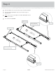
Step 2 å Turn eight CAM SCREWS (8F) into the LEGS (H and I). (8 used) 8F I I H H Page 6 420011 www.sauder.
Step 3 å Fasten the LEGS (H and I) to the ENDS (A and B). Tighten eight HIDDEN CAMS. 1 2 These edges must be even. Angled edge H S wi urfa H th ce CA IDD M EN S A These edges must be even. These holes must be here. I B I S wi urfa H th ce CA IDD M EN S H Angled edge These holes must be here. Angled edge www.sauder.
Step 4 å å Slide the SKIRTS* (K) onto the notched edges of the BOTTOM (E). å NOTE: The grooves in the SKIRTS and SHELF MOLDINGS should be closer to the floor. å *U.S. Patent No. 5,499,886 Slide the SHELF MOLDINGS* (N) onto the notched edges of the SHELF (F). Notched edge Groove Slide the SKIRT (K) onto the notched edge. Notched edge E th S wi AM ce C rfa EN Su IDD H K K F th S wi AM ce C rfa EN Su IDD H N N Slide the SHELF MOLDING (N) onto the notched edge. Groove Page 8 420011 www.sauder.
Step 5 å Fasten the SHELF (F) to the LEFT END (B). Tighten two HIDDEN CAMS. Don't worry. It isn't Rome. This can be built in a day. These holes are closer to this LEG. I B Sur HIDface w DEN ith CA MS F H Caution Risk of damage or injury. HIDDEN CAMS must be completely tightened. HIDDEN CAMS that are not completely tightened may loosen, and parts may separate. To completely tighten: www.sauder.
Step 6 å Fasten four METAL BRACKETS (4G) to the PANELS (J). Use four BLACK 9/16" LARGE HEAD SCREWS (1S). 4G å NOTE: Be sure the METAL BRACKETS are even with the edges of the PANELS. å Fasten the PANELS (J) to the SHELF (F). Use eight BLACK 1-15/16" FLAT HEAD SCREWS (113S). å J Fasten the PANELS (J) to the LEFT END (B). Use two BLACK 9/16" LARGE HEAD SCREWS (1S) through the METAL BRACKETS and into the LEFT END.
Step 7 å Fasten the UPRIGHT (C) to the SHELF (F). Tighten two HIDDEN CAMS. å Fasten the BOTTOM (E) to the LEFT END (B). Tighten two HIDDEN CAMS. å Fasten the BOTTOM (E) to the UPRIGHT (C). Use two BLACK 1-15/16" FLAT HEAD SCREWS (113S). 1st F C e fac Sur withDEN HID S M CA B Sur HIDface w DEN ith CA MS C E 113S BLACK 1-15/16" FLAT HEAD SCREW (2 used in this step) www.sauder.
Step 8 å Fasten the RIGHT END (A) to the BOTTOM (E) and SHELF (F). Tighten four HIDDEN CAMS. å NOTE: Use the provided Short Screwdriver to tighten the HIDDEN CAMS in the SHELF (F). å Fasten the RIGHT END (A) to the PANELS (J). Use two BLACK 9/16" LARGE HEAD SCREWS (1S) through the METAL BRACKETS and into the RIGHT END. å Push a CAM COVER (13P) onto each HIDDEN CAM.
Step 9 å Fasten the FOOT BRACKETS (6E) to the BOTTOM (E). Use six BLACK 9/16" LARGE HEAD SCREWS (1S). å å Slide the FEET (G) onto the FOOT BRACKETS (6E). Firmly push the CORNER CAPS (5E) onto the FEET (G) E 6E 6E G G G 1S 5E G BLACK 9/16" LARGE HEAD SCREW (6 used for the FOOT BRACKETS) 5E www.sauder.
Step 10 å å Carefully stand your unit upright. å NOTE: There are no pre-drilled holes in the PANEL MOLDINGS. The SCREWS will tighten into the grooves. å Center a SCREW COVER (18P) over the head of each SCREW and press firmly. å Push six BUMPERS (2M) into the LEGS (H and I) and PANELS (J). Pro Tip: Lift with your legs. And, you know, your arms. Fasten the PANEL MOLDINGS (M) to the PANELS (J). Use six SILVER 1-1/8" FLAT HEAD SCREWS (10S).
Step 11 å Fasten the LIFT TABLE MECHANISMS (23M) to the TOP (D). Use six BLACK 9/16" LARGE HEAD SCREWS (1S). å NOTE: Be sure to position the LIFT TABLE MECHANISMS on the TOP exactly as shown. 1S BLACK 9/16" LARGE HEAD SCREW (6 used in this step) 23M The holes are closer to this edge. D 23M www.sauder.
Step 12 å Fasten the SUPPORT BRACKETS (37G) to the LIFT TABLE MECHANISMS (23M). Use four WASHERS (13M), NUTS (24M), and BLACK 3/4" MACHINE SCREWS (92S). 92S 24M BLACK 3/4" MACHINE SCREW (4 used in this step) 13M 37G 23M D 23M 37G 24M Page 16 13M 420011 www.sauder.
Step 13 å å IMPORTANT: You will need someone's help in this step. å å NOTE: Do not overtighten the SCREWS (85S). å å NOTE: Be careful when lining up the holes in the MECHANISMS with the holes in the ENDS as to not damage any parts. Fasten the TOP (D) to the ENDS (A and B). Use two BUSHINGS (91M) and two BLACK 3/4" PAN HEAD SCREWS (85S) through the exact holes shown in the LIFT TABLE MECHANISMS (23M) and into the holes in the ENDS. Then, fasten the TOP (D) to the ENDS (A and B).
Step 14 å Fasten the BRACE (L) to the SUPPORT BRACKETS (37G) on the LIFT TABLE MECHANISMS (23M). Use four WASHERS (13M), NUTS (24M), and BLACK 1-1/4" MACHINE SCREWS (93S). Almost time to celebrate! With a nap. 93S BLACK 1-1/4" MACHINE SCREW (4 used in this step) 13M 24M L 37G 24M 23M 93S 23M 13M 37G Page 18 420011 www.sauder.
Step 15 å å å IMPORTANT: Do not place valuables in the storage space. NOTE: Please read the back pages of the instruction booklet for important safety information. This completes assembly. Clean with your favorite furniture polish or a damp cloth. Wipe dry. And to celebrate, why not share your success story? 40 lbs. 25 lbs. 40 lbs. total www.sauder.
420011 Utilisez les instructions d’assemblage en français avec les schémas étape par étape du manuel d’instruction en anglais. Chaque étape en français correspond à la même étape en anglais. La pièce devant être attachée à l’élément est représentée en gris sur les schémas de chaque étape pour plus de précision. Comparer la “Liste de pièces” ci-dessous avec la “PART IDENTIFICATION” du manuel en anglais pour vous familiariser avec les pièces avant l’assemblage.
ÉTAPE 1 ÉTAPE 6 Ne pas serrer les EXCENTRIQUES ESCAMOTABLES dans cette étape. Fixer quatre CONSOLES EN MÉTAL (4G) aux PANNEAUX (J). Utiliser quatre VIS TÊTE LARGE 14 mm NOIRES (1S). Assembler l'élément sur un sol à moquette ou sur le carton vide pour éviter d'endommager l'élément ou le sol. REMARQUE : S'assurer que les CONSOLES EN MÉTAL sont à fleur des chants des PANNEAUX. Enfoncer dix-huit EXCENTRIQUES ESCAMOTABLES (1F) dans les EXTRÉMITÉS (A et B), le MONTANT (C), le DESSOUS (E) et la TABLETTE (F).
ÉTAPE 9 ÉTAPE 13 Fixer les SUPPORTS DE PIED (6E) au DESSOUS (E). Utiliser six VIS TÊTE LARGE 14 mm NOIRES (1S). IMPORTANT : Faire appel à une autre personne pour cette étape. Faire glisser les PIEDS (G) sur les SUPPORTS DE PIED (6E). Appuyer fermement les COUVERCLES DE COIN (5E) sur les PIEDS (G). Fixer le DESSUS (D) aux EXTRÉMITÉS (A et B).
420011 Use estas instrucciones de ensamblaje en español junto con las figuras paso-a-paso provistas en el folleto inglés. Cada paso en español corresponde al mismo paso en inglés. Se destacan las figuras de cada paso con una tonalidad oscura para mostrar precisamente cual parte se debe montar a la unidad. Compare la “Lista de Part” abajo con la “Part Identification” en el folleto en inglés para familiarizarse con Las partes de ensamblaje.
PASO 1 PASO 6 No apriete los EXCÉNTRICOS ESCONDIDOS en este paso. Fije cuatro SOPORTES DE METAL (4G) a los PANELES (J). Utilice cuatro TORNILLOS NEGROS DE CABEZA GRANDE de 14 mm (1S). Ensamble la unidad sobre un piso alfombrado o sobre el cartón vacío para evitar rayar la unidad o el piso. NOTA: Asegúrese de que los SOPORTES DE METAL estén nivelados con los bordes de los PANELES.
PASO 9 PASO 13 Fije los SOPORTES DE PATA (6E) al FONDO (E). Utilice seis TORNILLOS NEGROS DE CABEZA GRANDE de 14 mm (1S). IMPORTANTE: Necesitar la ayuda de otra persona para este paso. Deslice las PATAS (G) sobre los SOPORTES DE PATA (6E). Presione firmemente las CUBIERTAS DE ESQUINA (5E) sobre las PATAS (G). PASO 10 Fije el PANEL SUPERIOR (D) a los EXTREMOS (A y B).
WARNING Please use your furniture correctly and safely. Improper use can cause safety hazards, or damage to your furniture or household items. Carefully read the following chart. Look out for: What can happen: How to avoid the problem: • Overloaded shelves. • Risk of injury. • Top-heavy furniture can tip over. • Overloaded shelves can break. • Never exceed the weight limits shown in the instructions. • Work from bottom to top when loading shelves. Place the heavier items on the lower shelves.
5-YEAR LIMITED WARRANTY 1. Sauder Woodworking Co. (Sauder®) provides limited warranty coverage to the original purchaser of this product for a period of five years from the date of purchase against defects in materials or workmanship of Sauder furniture components. As used in this Warranty, “defect” means imperfections in components which substantially impair the utility of the product. This Warranty gives you specific legal rights, and you may also have other rights which vary from state to state. 2.
Dear Valued Customer: So, how did it go? Thanks so much for choosing Sauder® furniture. I hope the purchase and assembly process was a positive experience and you feel good about the furniture you just built. If you need assistance or want to learn more, please contact our award-winning, Ohio-based customer service team at 800-523-3987 or Sauder.com. Set a world record for speed? Feeling good about yourself? Nice. Get social with it on any of these quality share sites.