4000121771-2.02.03 Instructions for Use Installation and Servicing To be left with the user Themaclassic F24E PLUS Fanned Flue Combination Boiler G.C.No. 47-920-37 Themaclassic F30E PLUS Fanned Flue System Boiler G.C.No. 47-920-38 Hepworth Heating Ltd., Nottingham Road, Belper, Derbyshire.
Guarantee Registration Thank you for installing a new Saunier Duval appliance in your home. Saunier Duval appliances' are manufactured to the very highest standard so we are pleased to offer our customers’ a Comprehensive Guarantee. This product is guaranteed for 24 months from the date of installation or 30 months from the date of manufacture, whichever is the shorter, for parts.
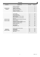
Contents CONTENTS INSTRUCTION FOR USE INSTALLATION INSTRUCTIONS SERVICING INSTRUCTIONS DESCRIPTION SECTION Important Information Draining and Filling Appliance Introduction Appliance Safety Devices Maintenance and Servicing Controls and Lighting Programmer instructions for use PAGE No.
Important Information Gas safety (Installation and use) Regulations All external wiring between the appliance and the electrical supply and earthing requirements shall comply with the current IEE Regulations. In your interests and that of gas safety, it is the law that ALL gas appliances are installed and serviced by a competent person in accordance with the regulations. Connection of the boiler and system controls to the mains supply must be through a common isolator and must be fused at 3A, maximum.
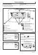
Draining and Filling 11900 Caution: The boiler is installed as part of a sealed system which must only be drained and filled by a competent person. If the mains electricity and gas are to be turned off for any long periods during severe weather, it is recommended that the whole system, including the boiler, refer to diagram 1, should be drained to avoid the risk of freezing. Make sure that, if fitted, the immersion heater in the cylinder is switched off. If in doubt, consult your servicing company.
Appliance Safety Devices Air flow rate safety device Frost protection If the flue is obstructed, even partially, the built in safety system will turn the boiler OFF, the fan will continue to run. The boiler will be ready to operate when the fault has been cleared. The appliance has a built in frost protection device that protects the boiler from freezing.
Controls and lighting Central heating adjustment Domestic hot water The temperature of the water in the central heating circuit can be set between, approx. 38OC and 87OC. The temperature can be adjusted from approx. 38°C up to 65°C.
Controls and lighting 4. Central heating temperature adjustment: 7. If a fault occurs: • The green running light will change to a red flashing light and the display will flash the letter ‘F’ with the type of fault. • Press button twice, is displayed and the current temperature setting flashes. • Reset the boiler: Switch the boiler OFF ( 0 ), wait for five seconds. Switch the boiler ON ( I ), the boiler is reset.
Programmer instructions for use Setting the time. press "+" and , and the will be displayed along with 0 to 24 hour ON / OFF settings and 1 to 7 days of the week. Make sure there is an electrical supply to the boiler and the boiler is switched ON ( I ). Set ON / OFF times at 30min intervals for each day 1 to 7 of the week. four times, is displayed and the time Press button will flash, press - or + to set the correct time (24hr clock).
1 Technical Data F24E PLUS F30E PLUS Heat input (max) NET Q Heat input (min) NET Q Heat output (max) GROSS P Heat output (min) GROSS P Efficiency - Sedbuk D Maximum heating temperature Expansion vessel effective capacity 32,6 kW 111,231 BTU/H 12,5 kW 42,650 BTU/H 29,6 kW 100,995 BTU/H 10,3 kW 35,144 BTU/H 78,3% 87° C 79,6% 87° C 6,5 l 8l 0,5 bar 125 l 0,5 bar 156 l maximum service pressure 3 bar 3 bar Expansion vessel charge pressure Maximum system capacity at 75°C RED Safety valve, 25,9 kW 88,3
2 General Information IMPORTANT NOTICE. In GB the following Codes of Practice apply: Where no British Standards exists, materials and equipment should be fit for their purpose and of suitable quality and workmanship. BS4814, BS5440 Part 1 and 2, BS5449, BS5546 Part 1, BS6700, BS6798, BS6891 and BS7074 Part 1 and 2, BS7478, BS7593, BS7671. Refer to Manual Handling Operations, 1992 regulations. In IE: I.S.813, BS5546, BS5449, BS7074, BS7593.
1 Bypass fully shut 2 Open 1/4 turn 3 Open 1/2 turn 4 Open 1 turn 5 Open 2 turns 11357 3 Heating System Design (10 kPa = 1 m WG) Diagram 3.1 Boiler * •The boiler is fitted with an adjustable automatic bypass. TABLE 1. FLOW RATE Model Minimum flow rate F 24 E plus ? F 30 E plus 21.26 litres per minute This is equal to 20°C differential at maximum heat input Bypass valve Drain point Ensure that under no circumstances does the flow rate drop below the figure specified, see Table 1.
5 Boiler Schematic 1 - Fan. 2 - Air pressure switch. 3 - Heat exchanger. 4 - Overheat thermostat. 5 - Combustion chamber. 6 - Expansion vessel. 7 - Flame sense electrode. 8 - Burner. 9 - Ignition electrode. 10 - Pump. 11 - Heating thermistor. 12 - Ignition unit. 13 - By-pass. 14 - Gas valve. 2 1 11422 15 - Loss of water sensor.
6 Boiler Location, Flue and Ventilation 11651 6.1 Boiler Location The recommended clearances are shown in diagram 6.1. 300mm 50mm above boiler (rear flue only) Note: The boiler must be mounted on a flat wall which is sufficiently robust to take its weight when full. If in doubt, expert advice should be obtained, in the event of the wall being found not suitable. * The minimum acceptable spacings from the terminal to obstructions and ventilation openings are shown in diagram 6.2.
6 Boiler Location, Flue and Ventilation 6.2 Terminal guard, see diagram 6.3. A terminal guard is required if persons could come into contact with the terminal or the terminal could be subject to damage. If a terminal guard is required, it must be positioned to provide a minimum of 50mm clearance from any part of the terminal and to be central over the terminal. A suitable terminal guard type K3 can be supplied by: 11508 Tower flue components Ltd. Morley road Tonbridge Kent TN9 1RA 6.
7 Fixing Jig The fixing jig is made up as follows: A - Heating return fitting with isolating valve. B - Cold water inlet fitting with isolating valve. The cold water inlet restrictor supplied with boiler is fitted when the boiler is installed. Refer to Section 9. C - Heating flow fitting with isolating valve. D - Domestic hot water outlet. E - Gas service cock. Other components within the fixing jig pack. F - Hanging bracket G - wall template J - sealing washers and screws Diagram 7.
8 Boiler Preparation and System Connections 9719 8.1 Cutting the flue hole • Remove the wall template, follow the instructions given on the wall template. • Position the wall template, taking due regard of the minimum clearances for the selected flue application, see diagram 8.1. • Horizontal Rear hole cutting • Mark position of Rear flue outlet hole from template, then remove template, before cutting, for use, later. The core drill used should be 115 mm diameter.
9 Boiler Installation 9.1 Sheet metal parts WARNING: When installing or servicing this boiler, care should be taken when handling the edges of sheet metal parts to avoid the possibility of personal injury. 9.2 Installing the boiler IMPORTANT NOTE: The system must be thoroughly flushed using a propriety cleanser from Fernox or Sentinel to eliminate any foreign matter and contamination e.g. metal filings, solder particles, oil, grease etc. Solvent products could cause damage to the system.
9 Boiler Installation 9.3 Heating safety valve (3 bar RED) and domestic safety valve (10 bar BLUE) discharge, refer to diagrams 9.4. DOMESTIC SAFETY VALVE(10 bar BLUE) Two short discharge pipes and washers are supplied in the fittings pack, fit these to the heating safety valve 3 bar and the domestic water safety valve 10 bar. The discharge must be extended using pipe not less than 15mm. od. to discharge in a visible position outside the building, facing downward preferably over a drain.
A RUBBER SEALING COLLAR 10311 10313 10 Horizontal Rear Flue Installation 40mm B E C G F H STANDARD FLUE ASSEMBLY I D Horizontal Rear flue kit PLASTIC INTERNAL FLANGE Diagram 10.1 X 40mm 10310 70mm (2.) Outside wall face INNER WALL (1.) The combined kits A2009700 include - Flue duct pipe ....................................................... A - Air duct pipe ........................................................... B - External rubber sealing collar ..............................
SELF ADHESIVE SEALS SAMPLE POINT SELF ADHESIVE GASKET EARTH LEAD 11431 PLASTIC INTERNAL FLANGE 10234 10 Horizontal Rear Flue Installation POWER SUPPLY LEAD INNER WALL FAN SENSOR PLUG ADAPTOR STANDARD FLUE ASSEMBLY FAN RETAINING BOLT Diagram 10.7 10315 Diagram 10.5 RESTRICTOR SELF ADHESIVE GASKET SECURING SCREW (2 OFF) FLUE HOOD Diagram 10.8 ADAPTOR Diagram 10.6 10.4 Flue Hood Outlet Restrictor, refer to diagram 10.
The Horizontal Telescopic Top Flue, Kit No. A2004500 11886 11 Horizontal Telescopic Top Flue Installation SIDE FLUE Suitable for installations that require a flue length "L" from 430 minimum to 660 maximum. If longer flueing is required extensions and bends are available, see note below. L If the flue length, see diagram 11.2. is less than 430 'L' Do Not cut this flue but use the horizontal top flue 86285. 70mm Note: Additional 1 metre extensions, 90° and 45° bends are available.
11 Horizontal Telescopic Top Flue Installation 11879 11.3 Installation of telescopic flue assembly STEP 1. • Remove the elbow (D) and the telescopic flue assembly (A) from the flue kit. FLUE LENGTH Outside wall face • Refer to Step 1. diagram 11.3. Fit the telescopic flue assembly (A) into the prepared hole in the wall. Position the elbow (D) on the boiler, do not secure. Position the telescopic flue assembly (A) as it would be fitted. 90mm (D) • Refer to Step 2. diagram 11.3.
12a.1 The Horizontal Top flue - kit 86285 11886 12 Horizontal Top Flue Installation SIDE FLUE Suitable for installations that require a max. flue length "L" of 740mm. If a shorter flue length is required, the flue can be cut to a min. length"L" of 260mm rear or 300mm side. See diagram 12a.2 for min. flue lengths. L 70mm 12a.2 Flue systems rear and side, refer to diagram 12a.1. 65mm 12a.3 Flue cutting, refer to diagram 12a.3.
12a.4 Installation of horizontal top flue assembly Outside wall face Important: If the flue has been cut, ensure that there are no burrs that could damage the ‘O’ ring. L • Remove the backing from the self adhesive gasket (H) and carefully fit gasket to base of elbow (C). 11643 12 Horizontal Top Flue Installation Flue centre line CL 90mm • Fit both ‘O’ rings (J) into the flue elbow (C), one at the inlet, one at the outlet.
13 Electrical Connection WARNING: This appliance must be earthed. This appliance must be wired in accordance with these instructions. Any fault arising from incorrect wiring cannot be put right under the terms of the Saunier Duval guarantee. 13.1 Mains Cable All system components must be of an approved type. 13.2 Voltage Free External Controls Electrical components have been tested to meet the equivalent requirements of the BEAB. Do not interrupt the mains supply with a time switch or programmer.
13 Electrical Connection 13.3 Mains Voltage External Controls WARNING: UNDER NO CIRCUMSTANCES MUST ANY MAINS VOLTAGE BE APPLIED TO ANY OF THE TERMINALS ON THE VOLTAGE FREE HEATING CONTROLS CONNECTION TERMINAL. STRAIN RELIEF When mains voltage external controls are used, remove the MAINS VOLTAGE HEATING CONTROLS CONNECTION PLUG from the fittings pack and install on the control interface PCB as follows.
14 Commissioning Important: The commissioning and first firing of the boiler must only be done by a competant person. Air in pipes Gas installation Important: A central heating system can not operate correctly unless it is filled with water and air bled from the system. If these conditions are not met the system may be noisy. If conversion from G20 to 30 or 31 is required, refer to section 13.
6. • Bleed each radiator to remove air, ensure all bleed screws are re-tightened. • If necessary repressurise the system, refer to procedure 4 • Leave cap open on automatic air vent. Ins 061a 5. 11548 14 Commissioning ➜ 8. • Open various hot water taps to bleed system Ins 062a 11524 7. • Ensure the display indicates a system pressure of 1.0 bar adjust if necessary. Adjust heating temperature to maximum.
14 Commissioning Bypass The boiler has a built-in bypass, see diagram 15.1. 9718 A The boiler is supplied with the bypass open half a turn. It should not be necessary to adjust the bypass, but if required ensure that under no circumstances does the flow rate fall below the figures specified, refer to Table 1. and diagram 1.1. (turn clockwise to close the valve). Diagram 15.
15 Boiler Settings Parameter 3 : Setting the minimum heating temperature This can be set to one of two values : 38°C or 50°C. Flue parameter following flue length - Rear Setting Flue length for F 24 E Flue length for F 30 E 0 3 1 38°C Factory setting 2 3 0,3 m 0,3 m 4 0,6 m 0,6 m 5 0,9 m 0,9 m 6 1,2 m 1,2 m 7 1,5 m 1,5 m Parameter 4 : Setting the maximum heating temperature This can be set to one of four values : 50°C, 73°C, 80°C and 87°C.
16 Changing Gas Type Should it be necessary to change the gas type, a conversion kit with instructions will be required. Press the mode button for about 10 seconds, Use + or - to display code ‘35’, Press the mode button to confirm, The display idicates line 23 in the data menu, The figure on the left is the data, the one on the right is the setting for the data.
17 Routine Cleaning and Inspection 9532 REMEMBER, when replacing a part on this appliance, use only spare parts that you can be assured conform to the safety and performance specification that we require. Do not use reconditioned or copy parts that have not been clearly authorised by Hepworth Heating. PRODUCTS SAMPLING POINT To ensure the continued efficient and safe operation of the boiler it is recommended that it is checked and serviced at regular intervals.
17 Routine Cleaning and Inspection To Drain the Domestic hot water circuit • Close boiler isolating valve (b). • Turn on one or more hot water taps. To Drain the boiler • Close isolating isolating valves (a) and (c). • Open the boiler drain valve (f). (a) HEATING RETURN (b) COLD WATER INLET (c) (f) HEATING FLOW BOILER DRAIN VALVE (d) DOMESTIC HOT WATER OUTLET Note: Isolating cocks water and gas are shown in the: OFF position GAS SERVICE COCK 9533 Diagram 17.1 9533 Diagram 17.
17 Routine Cleaning and Inspection 17.7 Combustion chamber cover retaining clip. • Unscrew and remove the two screws securing combustion chamber cover to combustion chamber, see diagram 17.5. 17.14 Sealed Chamber Cover - Seal Check Check the condition of the seal, replace as required. • Remove combustion chamber cover from boiler. To replace remove the old seal, thoroughly clean the casing sufaces. Fit the new seal, it is supplied to the correct length, see diagram 20.29. 17.
9742 17 Routine Cleaning and Inspection 9812 BURNER RETAINING SCREWS BURNER GUIDE 9818 AIR PRESSURE SWITCH SENSING TUBE 9815 9750 9817 FLUE HOOD Diagram 17.7 HEAT EXCHANGER FAN RETAINING BOLTS CLIP DOMESTIC WATER INLET FILTER HOUSING 11428 EARTH LEAD Diagram 17.9 FILTER Diagram 17.10 Diagram 17.8 RETAINING CLIP 11929 11928 POWER SUPPLY LEADS 9822 FAN SENSOR PLUG FLAT FILTER Diagram 17.
18 Fault Finding Before trying to operate the boiler make sure that : Overheat thermostat reset button • All gas supply cocks are open and that the gas supply has been purged of air. Refer to Section 20.10 to locate the overheat thermostat reset button. • The heating system pressure is at least 1 bar. Depress the button to reset. 9749 • There is a permanent mains supply to the boiler and that the polarity is correct. • The fuse on the PCB is intact. WARNING.
18 Fault Finding TYPE OF FAULT CHECK No display on control panel • 230V supply • PCB fuse • Connection between PCBs No domestic hot water No central heating (warning light of fault code displayed on control panel) • Loose connections on control board (PCB) • Connections on air pressure switch (electrical or tubes) disconnected • Faulty control or interface board (PCB's) • Water pressure, flashing pressure • Shortage of air or gas • Faulty temperature sensor • Overheating COMPONENT TESTING DATA COMPONE
18 Fault Finding Are the external heating controls calling for heat? NO Rectify fault on external controls. 10301 FAULT: NO HEATING YES Is the polarity correct? Rectify, check the 230V controls board. NO YES Connect 1 and 2 on J10, does boiler fire in central heating? NO Faulty main PCB. YES Faulty 230V controls board.
FAULT: NO HOT WATER, BUT THE HEATING IS WORKING Is the water pressure greater than 0.5 bar ? 9961 18 Fault Finding Insufficient water pressure. The appliance will not operate. Find out why the pressure is so low. NO YES Check the cold water inlet filter for dirt. Is the cold water tap fully open ? Check the heat exchanger for scaling. Is the water flow rate greater NO than 1.7l/min. (threshold figure). YES Is flow detector operating ? NO Change or clean it.
18 Fault Finding FAULT: THE BURNER LIGHTS, THEN GOES OUT. The flame is spreading across the whole burner, but not being detected. CHECK THE CHECK PROBE THE MAINS FAULT NOT FOUND With the power turned off, check the continuity between the spark electrode and terminal H24 on the control board (PCB). Check the connector on the end of the wire. Check that the spark electrode is pointing towards the flame. Check the spark electrode. Change it. 11798 If the problem persists, change the control board (PCB).
9966p 18 Fault Finding FAULT: THE WATER AT THE TAPS IS LUKE-WARM. Is the temperature higher if you reduce the flow through the taps? Check the 3-way valve is not passing into the radiators. (The radiators should stay cold in Summer setting) NO YES 9968p Check that the flow restrictor on the cold water inlet is fitted. Check the rate of flow. Check burner pressure is correct. FAULT: THE FAN DOES NOT START. Is there is 230V ac at fan during demand? NO Check continuity of fan harness.
FAN g/y br w g MICRO ACCUMULATOR HEATING ELEMENT AIR PRESSURE SWITCH b SENSE ELECTRODE 3 1 MICRO ACCUMULATOR VESSEL THERMISTOR IGNITION ELECTRODES p FAN SENSOR g or w WATER PRESSURE SENSOR IGNITER UNIT GAS CONTROL VALVE OVERHEAT THERMOSTAT bk bk 3 bk 4 1 PUMP CH bk b PLUG p y or gn b 2 g/y THERMISTOR CH CHASSIS EARTH wg THREE-WAY VALVE MAINS VOLTAGE HEATING CONTROLS PLUG REMOVE VOLTAGE FREE LINK 230V SWITCHED LIVE FROM OPTIONAL FROST STAT. 230V SWITCHED LIVE FROM HEATING CONTROLS.
20 Replacement of Parts To Drain the central heating circuit • Open drain valve fitted at the lowest point in the system. • Allow air into the system by opening a radiator bleed screw or the boilers drain valve (f). To Drain the Domestic hot water circuit • Close boiler isolating valve (b). • Turn on one or more hot water taps. To Drain the boiler • Close isolating valves (a), (b) and (c). • Open the boiler drain valve (f). • Turn on one or more hot water taps.
20 Replacement of Parts 9646 20.2 Fan, refer to Section 17.10 Before starting refer to the front of Section 20 Important information. • Remove the front panel, refer to Section 17.3. • Remove the sealed chamber cover, refer to Section 17.5. RETAINING CLIPS • Remove the fan, refer to Section 17.10. 20.3 Fan sensor, refer to diagram 17.8 Before starting refer to the front of Section 20 Important information. ELECTRICAL CONNECTORS • Remove the front panel, refer to Section 17.3.
20.10 Burner injector assembly, refer to diagram 20.5 and 20.6. 9819a 20 Replacement of Parts BURNER INJECTOR BAR Before starting refer to the front of Section 20 Important information. • Remove the front panel, refer to Section 17.3. • Lower the control panel, refer to Section 17.4. • Remove the sealed chamber cover, refer to Section 17.5. Diagram 20.5 • Remove the combustion chamber cover, refer to Section17.7. • Remove burner from boiler, refer to Section 17.9.
20 Replacement of Parts 20.14 Heat exchanger, refer to diagram 20.7. 20.16 Printed circuit board (PCB), refer to diagram 20.9. Before starting refer to the front of Section 20 Important information. • Remove the front panel, refer to Section 17.3. Before starting refer to the front of Section 20 Important information. • Remove the sealed chamber cover, refer to Section 17.5. • Remove the front panel, refer to Section 17.3. • Remove the combustion chamber cover, refer to Section 17.7.
20 Replacement of Parts ➜ 10212 ➜ ➜ 11424 230V CONTROLS BOARD ➜ ➜ CONTROL PANEL USER INTERFACE BOARD ➜ MAINS SWITCH Diagram 20.10 Before starting refer to the front of Section 20 Important information. HEX HEAD SCREW (4 OFF) • Unclip control panel user interface and hinge forward . Do not strain the cables. • Disconnect the electrical connections from the user inter face board. 9757 20.17 User interface board, refer to diagram 20.10.
20 Replacement of Parts 20.22 Reduced pressure zone valve (RPZ), refer to diagram 20.12. REDUCED PRESSURE ZONE VALVE (RPZ) Before starting refer to the front of Section 20 Important information. • Remove the front panel, refer to Section 17.3. ➜ • Pull out slotted metal clip securing pipe to RPZ. ➜ 11589 • Drain down the boiler only, refer to relevant part of diagram 20.1. ➜ • Lower the control panel, refer to Section 17.4. ➜ • Pull out slotted metal clip securing RPZ into housing, remove RPZ.
20 Replacement of Parts 20.26 Bypass valve, refer to diagram 20.15. SYSTEM WATER PRESSURE SENSOR BYPASS VALVE 9758 Before starting refer to the front of Section 20 Important information. • Remove the front panel, refer to Section 17.3. • Lower the control panel, refer to Section 17.4. ➜ Drain down the boiler, refer to relevant part of Section 20.1. Pull out slotted metal clip, ease out bypass valve from bypass valve housing. 20.27 Automatic air vent, refer to diagram 20.16.
20 Replacement of Parts 10018 20.30 Heating safety valve (3 bar RED), refer to diagram 20.19. Before starting refer to the front of Section 20 Important information. • Remove the front panel, refer to Section 17.3. GAS CONTROL VALVE • Lower the control panel, refer to Section 17.4. • Undo discharge pipe union nut. ➜ • Pull out slotted metal clip from valve body and remove valve. 20.31 Three-way valve head, refer to diagram 20.20.
20 Replacement of Parts 20.34 Domestic hot water plate to plate heat exchanger 20.35 Domestic safety valve (10 bar BLUE), refer to diagram 20.24. Before starting refer to the front of Section 20 Important information. Before starting refer to the front of Section 20 Important information. • Remove the front panel, refer to Section 17.3. • Remove the front panel, refer to Section 17.3. • Lower the control panel, refer to Section 17.4. • Lower the control panel, refer to Section 17.4.
20 Replacement of Parts 20.36 Micro accumulator vessel thermistor, refer to diagram 20.25. • Release the micro accumulator vessel heating element cable from the securing clips, note the routing of the cable for reassembly. Before starting refer to the front of Section 20 Important information. • Pull out micro accumulator vessel thermistor securing clip and remove thermistor from heating element. • Locate micro accumulator vessel thermistor, on top of the micro accumulation vessel. 20.
20 Replacement of Parts Replacing the expansion vessel • Lift up to remove the boiler from the wall. Before starting refer to the front of Section 20 Important information. • Remove sealed chamber cover, refer to Section 17.4. • Remove the combustion chamber cover, refer to Section 17.5. • For this operation the boiler must be removed from the wall. • Remove the fan, refer to Section 17.10. • Remove air pressure switch sensing tube from the side of the flue hood, see diagram 17.9.
20 Replacement of Parts 20.40 Sealed chamber cover seal, refer to diagram 20.29 Before starting refer to the front of Section 20 Important information. • Remove the front panel, refer to Section 17.3. SEALED CHAMBER COVER • Remove the sealed chamber cover, refer to Section 17.5. • Remove the old seal, thoroughly clean the casing. Fit the new seal, it is supplied to the correct length. Note: Ensure the seal is fitted correctly giving an air tight seal. SEAL FRONT CASING PANEL Diagram 20.
21 Spare parts When ordering spare parts, quote the part number and description, stating the appliance model number and serial number from the data badge. Short parts list No.