
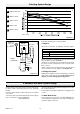
Technical data


18
4000121771-2
9 Boiler Installation
9.1 Sheet metal parts
WARNING: When installing or servicing this boiler, care should
be taken when handling the edges of sheet metal parts to avoid
the possibility of personal injury.
9.2 Installing the boiler
IMPORTANT NOTE: The system must be thoroughly flushed
using a propriety cleanser from Fernox or Sentinel to eliminate
any foreign matter and contamination e.g. metal filings, solder
particles, oil, grease etc.
Solvent products could cause damage to the system.
• Remove front panel, unscrew and remove the two retaining
screws from the bottom of the front panel. Remove front panel
by lifting up and forward.
• To remove the self adhesive wiring diagram label from the
document envelope. Fit the self adhesive wiring diagram label
to the inside of the front panel, put front panel in a safe place to
avoid damaging it.
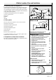
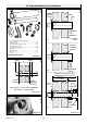
(Horizontal Rear Flue Only)
Note: Firstly remove the fan as described in section 10.3.
Fit the flue adaptor and gasket , refer to diagram 9.3, supplied
in the flue pack to the rear of the appliance, having first moved
and secured the blanking plate to the top outlet.
• If fitted ensure the plastic plugs are removed from water
and gas pipes. NOTE: There will be some spillage of water.
• Fit the cold water inlet restrictor (supplied in the document
envelope) into cold water inlet isolating valve, see diagram 7.1.
Important Note. With regards to the manual handling
operations, 1992 regulations, the following operation exceeds
the recommended weight for one man lift.
• Lift the boiler up and engage boiler onto the hanging bracket,
refer to diagram 7.1.
• Fit the washers between the boiler and isolating valves, see
diagram 7.1.
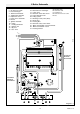
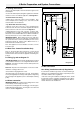
Diagram 9.2
10088
FILLING LOOP
EXTENSION
FILLING DEVICE
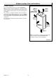
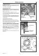
Diagram 9.1
DISCHARGE
SAFETY VALVE
PIPE
KNURLED
UNION NUT
finger tighten only
10315
Diagram 9.3
SECURING
SCREW
(2 OFF)
ADAPTOR
SELF
ADHESIVE
GASKET