
Instruction manual


3700R/3740 Refrigerated Sampler
Section 5 Routine Maintenance and Service
5-18
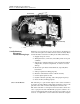
Figure 5-11 Distributor Gear Case Removal
5.20 Preliminary
Electronics
Troubleshooting Steps
Following are suggested areas to check before attempting to
service the microprocessor CPU and associated circuitry. These
checks should be made before looking at the CPU and memory.
1. Supply voltage is correct.
2. Wiring harnesses, connectors, and solder joints are in good
condition.
3. Appearance of physical damage, such as burned or broken
components, overly hot components, or evidence of water
damage.
4. Shorted or open diodes and transistors, especially drive
transistors.
5. Voltage regulators working properly.
6. Excessive current draw in some or all the circuitry.
7. Correct input signals to unit.
8. Crystal oscillator operating and at the proper frequency.
9. Reset circuitry working properly.
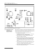
5.20.1 Circuit Boards The following is a general description of the 3700 controller’s
electronic circuitry. While reading this description, refer to the
pictorial views of the circuit boards (Figures 5-12 and 5-13).
The 3700 controller is a microprocessor-based device which exe-
cutes a program stored in ROM. The program (software) is a
series of instructions that tell the microprocessor what to do in
order to accomplish the various functions which the sampler
Ground Strap
Ground Strap