SDC 306 Microprocessor-controlled system control unit for solar thermal systems Installation and Operating Instructions IMPORTANT Before installing and using this device, you must read through the instructions carefully. Failure to observe the instructions and safety information contained in these installation and operating instructions will void the guarantee for the device described/installed. Store these instructions in a safe place. 15.06.
Installation and Operating Instructions Table of contents 1 2 3 SAFETY INSTRUCTIONS SYMBOLS AND ABBREVIATIONS DEVICE DESCRIPTION 3.1 3.2 4 5 4 5 6 Usage Device features 6 6 OVERVIEW OF DEVICE COMPONENTS DEVICE INSTALLATION 5.1 5.2 6 Opening the device (only by qualified personnel) Wall-mounted installation ELECTRICAL CONNECTION 6.1 6.
Installation and Operating Instructions 10.2.1 10.2.2 10.2.3 11 30 30 30 SYSTEM DIAGRAMS 11.1 11.2 11.3 11.4 11.5 11.6 11.7 11.8 11.9 11.10 11.11 11.12 11.13 11.14 11.15 11.16 11.17 11.18 11.
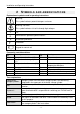
Installation and Operating Instructions 1 S AF E T Y INSTRUCTIONS This control unit must be disconnected from the mains before any installation and wiring work is carried out. This device may only be opened, connected and commissioned by trained personnel. In so doing, the relevant safety regulations, especially VDE 0100 must be adhered to.
Installation and Operating Instructions 2 SYMBOLS AN D AB B R E V I AT I O N S Explanation of symbols used in operating instructions: Warning! This symbol indicates potential dangers and errors Warning: 230 Volts This symbol indicates risk to life through high voltages.
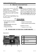
Installation and Operating Instructions 3 DEVICE DESCRIPTION 3.1 Usage The solar thermal controllers SDC 306 are high-performance, microprocessorcontrolled control devices used to control the function of solar thermal systems. Alternative use or use beyond this remit is not in accordance with its purpose. Incorrect usage can result in serious injury or death to the user or a third party and can harm the device or system and other material assets.
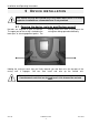
Installation and Operating Instructions 5 DEVICE I N S T AL L AT I O N This control unit may be installed only in dry rooms where there is no risk of explosion. Installation on a flammable base is not permitted. 5.1 Opening the device (only by qualified personnel) No tools are required to open the device. The upper part of the casing is locked to the lower part at two engagement points. The locking forces are such as to prevent the casing from being opened accidentally.
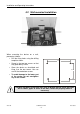
Installation and Operating Instructions 5.2 Wall-mounted installation When mounting the device on a wall, proceed as follows: • Drill the fixing holes using the drilling template shown. • Screw in the two top screws so that they protrude by 6 mm. • Open the device as described and hang it on the two screws. You can now fit the two bottom screws. • 126mm 84mm To avoid damage to the lower part of the casing, do not overtighten any of the screws. 118mm You drill into walls at your own risk.
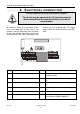
Installation and Operating Instructions 6 E L E C T R I C AL CONNECTION You must observe the safety instructions in chapter 1 The device may be opened only if it has been properly disconnected from the mains and there is no risk of reconnection. All electrical cables are connected to the unit in the lower part of the casing. The terminals on the right-hand side are those for the (low voltage) connections for sensor and flow meter. The 230 V connections are located on the left-hand side.
Installation and Operating Instructions General attachment regulations: • • used for the feedthrough on the 230 V side. For all attachment wires, cut the wire sheath to a length of approx. 6 – 8 cm and unisolate the wires by approx. 10 mm from the ends. In the case of flexible cables, provision must be made inside or outside the device for strain relief. The wire ends must be fitted with wire-end sleeves.
Installation and Operating Instructions 5 1 collector array, 1 storage cylinder, solid fuel boiler, return line monitor 6 1 collector array, 1 storage cylinder, auxiliary heating, return line temperature increase 7 1 collector array, 1 storage cylinder, auxiliary heating, return line monitor 8 9 10 11 1 collector array, 2 storage cylinders (hot water and buffer), return line temperature increase 1 collector array, 2 storage cylinders (hot water and buffer), return line temperature increase 1 coll
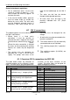
Installation and Operating Instructions 6.2 Attachment of temperature sensor The SDC 306 devices work with precise platinum temperature sensors of type PT1000. Between 2 and 5 sensors are required, depending on the scope of function. Installation/wiring of temperature sensor: Install the sensors at the requisite places on the collector and the storage cylinder. In so doing, ensure good temperature transmission and, if necessary, use a thermally conductive paste.
Installation and Operating Instructions 7 COMMISSIONING Commission your control unit in the following sequence: ? Are the collector and storage cylinder sensors correctly mounted ? Has the correct sensor type been selected (PT1000)? Yes Select and install the correct sensor No ? Is the power cable for the pump connected correctly to the pump and the control unit? Yes No §If the pump is powered directly via a mains cable: does the pump work? Yes No Unplug the mains plug Unplug the mains plug
Installation and Operating Instructions 8 O P E R AT I O N / I N D I C AT O R S 8.1 Overview of displays and operating controls The SDC 306 control unit is operated comfortably and simply by means of 4 buttons. The operating buttons allow you to: • Access display values • Enter device settings The graphic symbols on the display unit lead you simply through the operating structure and provide a clear overview of the current menu options, display values and parameters.
Installation and Operating Instructions 8.2 Display – maximum display In the following graphic, all symbols that can appear on the display during operation are displayed simultaneously. In real-time operation, depending on the menu position, only some of these symbols will appear.. Main menu Display values Allocation of measuring points Status display 8.3 Explanation of graphic symbols The meaning of the individual symbols is given in the table below.
Installation and Operating Instructions Graphic symbol Td Description Display values Temperature difference Display during operation start Start value Appears when start values are displayed stop Stop value Appears when stop values are displayed min Min. value Appears when minimum values are displayed max Max.
Installation and Operating Instructions Temperature sensor 1 Temperature sensor 2 Temperature sensor 3 Temperature sensor 4 Temperature sensor 5 Position of sensors Collector array Is displayed together with the relevant sensor number. If there are two collector arrays, a 1 or 2 is displayed on the righthand side of the collector symbol. Top of storage cylinder Is displayed together with the relevant sensor number.
Installation and Operating Instructions Position of sensors Sensor in return line if there is a return line monitor Is displayed together with the relevant sensor number. Sensor in return line if there is increase in temperature through a return line monitor Is displayed together with the relevant sensor number. Solid fuel boiler Is displayed together with the relevant sensor number. Collector supply Is displayed together with the relevant sensor number.
Installation and Operating Instructions Reference sensors for source and sink flash alternately. System time Is displayed in the programming menu. Status display Solar circuit pump Symbol rotates when the solar circuit pump is switched on Switching output 1 is active Appears if switching output 1 is active (on). Switching output 2 is active Appears if switching output 2 is active (on). Switching outputs 3 and 4 are active (switched in parallel) Appears if switching output 3 and 4 are active (on).
Installation and Operating Instructions 8.4 Example of device operation Once you have familiarised yourself with the menu descriptions as described in the “Operating menus“ chapter, you can practice by carrying out the operating steps. The starting point is the current collector temperature on the “Info” menu. Aim: change to “Solar circuit Td stop” circuit from 3K to 4K in “Program” menu. This example relates to configuration (system diagram) 1.
Installation and Operating Instructions 9 MENU STRUCTURE To facilitate simple operation of the device, the device, operating and display functions are combined into 4 groups (= main menu). The four menus • Information • Program • Manual operation • Basic setting Menu Information Program provide information on your solar thermal system. The currently active menu is displayed by means of the relevant graphic symbol in the top row of the display.
Installation and Operating Instructions 9.2 “Program” All changeable parameters can be checked in this menu and changed if necessary. Common values are set at the factory, which will generally ensure that the system functions correctly. i menu The number of displayed values depends on the type of controller and the additional functions set. Only the values required in each case are displayed.
Installation and Operating Instructions 9.3 “Manual operation” For the purposes of servicing and testing, the solar thermal system can be operated manually. To facilitate this, the 230 V or switching outputs or the potential-free output can be switched on and off. During manual operation, there is no automatic menu control of the system.
Installation and Operating Instructions Display Parameters Value C 00 01 10 0000 0 1 120 11 1 20 0 21 22 0.0 0.
Installation and Operating Instructions 9.4.1 Code entry The “C” on the left flashes. Press the OK key. Does the first digit after the C flash? Yes No System error Press the up button, then +1 Press the down button, then -1 Enter the required digit and confirm with OK ? First position entered correctly? Yes Press the reset button No §Enter the 2nd, 3rd and 4th digits in exactly the same way as the 1st digit.
Installation and Operating Instructions 10 C O N T R O L L E R FUNCTIONS • Functions for system protection and system monitoring • Additional functions The SDC 306 controllers include comprehensive functions for controlling and monitoring the solar thermal system. A basic distinction is made between: • Control functions for loading the storage cylinder 10.
Installation and Operating Instructions 10.1.2 Yield estimation / yield metering For the purposes of yield estimation (heat quantity), the collector sensor serves as a reference sensor for the hot flow, the storage cylinder sensor at the bottom serves as a reference sensor for the cool return line. The volume flow, type of glycol and glycol concentration are entered in the control unit. A daily yield value is calculated from these five values and can be 10.1.3 displayed.
Installation and Operating Instructions 10.1.7 Return line monitor In the case of solar thermal systems with auxiliary heating and where there is a heat station, the return line of the heating circuit is layered into the storage cylinder. Depending on the temperature difference between the return line and the solar storage cylinder in the middle, a 3-way valve is triggered in order to layer the return 10.1.8 line at the bottom or centre of the solar storage cylinder.
Installation and Operating Instructions 10.1.12 Priority switching The solar circuit has priority for loading the storage cylinder. If the temperature in the solar circuit is too low or if the maximum temperature of the storage cylinder is reached, the system switches to the swimming pool circuit/secondary circuit. An increase in temperature of the collector is monitored.
Installation and Operating Instructions 10.2 System monitoring If an error occurs, the ! symbol will always flash. 10.2.1 Sensor monitoring The sensors required for the control functions and their connection cables are monitored for breakage and short circuit. If a defective sensor is recognised by the Important: The use of incorrect temperature sensors can therefore also lead to one of the error messages. ! symbol is displayed. software, the The source of the error can be found by scrolling.
Installation and Operating Instructions 11 S Y S T E M D I AG R AM S There are 19 main configurations for solar control unit SDC 306. Output A1 is switched via the solar control circuit. The two outputs A3 (230V) and A4 Control circuit Solar circuit Control circuit R2 Control circuit R3 i (potential-free) are switched in parallel via the control circuit R2. Output A2 is switched via the control circuit R3.
Installation and Operating Instructions 11.1 Basic system diagram 1: 1 collector array, 1 storage cylinder System 1 has one collector surface and one storage cylinder.
Installation and Operating Instructions 11.2 Basic system diagram 2: 1 collector array, 1 storage cylinder, auxiliary heating, anti-Legionnaire’s disease System 2 has one collector surface, one and the anti-Legionnaire’s disease function storage cylinder, one auxiliary heating (thermostat, timeframe a preset, fixed function and one anti-Legionnaire’s disease period). Heat metering is also possible, e.g. function. The control unit controls the solar using an impeller flow meter.
Installation and Operating Instructions 11.3 Basic system diagram 3: 1 collector array, 1 storage cylinder, auxiliary heating, circulation System 3 has one collector surface, one function (thermostat, timeframe) and the storage cylinder, one auxiliary heating impulse-controlled circulation (impulse) or function and one timer-controlled or thermal circulation (thermostat, 2 impulse-controlled circulation. The control timeframes).
Installation and Operating Instructions 11.4 Basic system diagram 4: 1 collector array, 2 storage cylinders (hot water), thermal transfer, auxiliary heating System 4 has one collector surface, two (temperature difference regulation, storage cylinders, a transfer function and an timeframe) and the auxiliary heating auxiliary heating function. The control unit (thermostat, timeframe). Heat metering is controls the solar function (temperature also possible, e.g.
Installation and Operating Instructions 11.5 Basic system diagram 5: 1 collector array, 1 storage cylinder, solid fuel boiler, return line monitor System 5 has one collector surface, one thermostat) and the return line temperature storage cylinder, one solid fuel boiler and increase (temperature difference one return line monitor. The control unit regulation). Heat metering is also possible, controls the solar function (temperature e.g. using an impeller flow meter.
Installation and Operating Instructions 11.6 Basic system diagram 6: 1 collector array, 1 storage cylinder, auxiliary heating, return line temperature increase System 6 has one collector surface, one auxiliary heating (thermostat, timeframe) storage cylinder, one auxiliary heating and the return line temperature increase function (thermostat, timeframe) and one (temperature difference regulation). Heat return line temperature increase. The metering is also possible, e.g.
Installation and Operating Instructions 11.7 Basic system diagram 7: 1 collector array, 1 storage cylinder, auxiliary heating, return line monitor System 7 has one collector surface, one auxiliary heating (thermostat, timeframe) storage cylinder, one auxiliary heating and the return line monitor (temperature function and one return line monitor. The difference regulation). Heat metering is also control unit controls the solar function possible, e.g. using an impeller flow meter.
Installation and Operating Instructions 11.8 Basic system diagram 8: 1 collector array, 2 storage cylinders (hot water and buffer), return line temperature increase System 8 has one collector surface, two storage cylinders, priority logic), and the storage cylinders, one solid fuel boiler and return line temperature increase (temperature difference regulation). Heat one return line temperature increase. The control unit controls the solar function metering is also possible, e.g.
Installation and Operating Instructions 11.9 Basic system diagram 9: 1 collector array, 2 storage cylinders (hot water and buffer), return line temperature increase System 9 has one collector surface, two storage cylinders, priority logic), and the storage cylinders, one solid fuel boiler and return line temperature increase (temperature difference regulation). Heat one return line temperature increase. The control unit controls the solar function metering is also possible, e.g.
Installation and Operating Instructions 11.10 Basic system diagram 10: 1 collector array, 1 storage cylinder, swimming pool, return line temperature increase System 10 has one collector surface, one storage cylinder and swimming pool, priority storage cylinder, one swimming pool and logic), and the return line temperature one return line temperature increase. The increase (temperature difference control unit controls the solar function regulation).
Installation and Operating Instructions 11.11 Basic system diagram 11: 1 collector array, 1 storage cylinder, swimming pool, return line temperature increase System 11 has one collector surface, one storage cylinder and swimming pool, priority storage cylinder, one swimming pool and logic), and the return line temperature one return line temperature increase. The increase (temperature difference control unit controls the solar function regulation).
Installation and Operating Instructions 11.12 Basic system diagram 12: 1 collector array, 1 storage cylinder, swimming pool, auxiliary heating System 12 has one collector surface, one and swimming pool, priority logic), and the storage cylinder, one swimming pool and auxiliary heating function (temperature one auxiliary heating. The control unit difference regulation, timeframe). Heat controls the solar function (temperature metering is also possible, e.g.
Installation and Operating Instructions 11.13 Basic system diagram 13: 1 collector array, 1 storage cylinder, swimming pool, auxiliary heating System 13 has one collector surface, one and swimming pool, priority logic), and the storage cylinder, one swimming pool and auxiliary heating (temperature difference one auxiliary heating function. The control regulation, timeframe). Heat metering is unit controls the solar function (temperature also possible, e.g.
Installation and Operating Instructions 11.14 Basic system diagram 14: 2 collector arrays, 1 storage cylinder, auxiliary heating System 14 has two collector surfaces, one metering is also possible, e.g. using an storage cylinder and one auxiliary heating impeller flow meter. function. The control unit regulates the solar function (temperature difference regulation K1 = Collector array 1 for 2 collector arrays) and the auxiliary K2 = Collector array 2 heating (thermostat, timeframe).
Installation and Operating Instructions 11.15 Basic system diagram 15: 2 collector arrays, 1 storage cylinder, return line temperature increase System 15 has two collector surfaces, one (temperature difference regulation). Heat storage cylinder and one return line metering is also possible, e.g. using an temperature increase. The control unit impeller flow meter.
Installation and Operating Instructions 11.16 Basic system diagram 16: 1 collector array, 1 storage cylinder, circulation, anti-Legionnaire’s disease System 16 has one collector surface, one timeframe fixed, preset period) and the impulse-controlled circulation (impulse) or storage cylinder, one timer-controlled or impulse-controlled circulation pump and one thermal circulation (thermostat, 2 timeframes). Heat metering is also possible, Anti-Legionnaire’s disease function.
Installation and Operating Instructions 11.17 Basic system diagram 17: 1 collector array, 2 storage cylinder, thermal transfer, return line temperature increase System 17 has one collector surface, two the thermal transfer (temperature difference storage cylinders, one thermal transfer regulation, timeframe) and the return line function and one return line temperature temperature increase (temperature increase. The control unit controls the solar difference regulation).
Installation and Operating Instructions 11.18 Basic system diagram 18: 1 collector array, 2 storage cylinder, thermal transfer, return line monitor System 18 has one collector surface, two thermal transfer (temperature difference storage cylinders, one thermal transfer regulation, timeframe) and the return line function and one return line monitor. The monitor (temperature difference regulation). control unit controls the solar function Heat metering is also possible, e.g.
Installation and Operating Instructions 11.19 Basic system diagram 19: 1 collector array, 2 storage cylinder, thermal transfer, return line monitor (with solid fuel boiler) System 19 has one collector surface, two regulation, timeframe) and the return line storage cylinders, one thermal transfer monitor (temperature difference regulation). Heat metering is also possible, e.g. using function and one return line monitor. The control unit controls the solar function an impeller flow meter.
Installation and Operating Instructions Information I Current collector temperature (E1) Minimum collector temperature (E1) Maximum collector temperature (E1) Current storage cylinder temperature at bottom (E2) Minimum storage cylinder temperature at bottom (E2) Maximum storage cylinder temperature at bottom (E2) Current storage cylinder temperature at top (E4) Minimum storage cylinder temperature at top (E4) Maximum storage cylinder temperature at top (E4) Current temperature of thermal transfer storage c
Installation and Operating Instructions 12 R E C T I F I C AT I O N O F F AU L T S There are basically two kinds of system fault: • Faults that are recognised by the control unit and which it can therefore indicate • Faults that cannot be indicated by the control unit 12.
Installation and Operating Instructions 12.2 Faults without error message Faults and errors that are not displayed can be checked against the following table and possible causes and sources of error identified. If, based on the description, fault rectification is not possible, you will need to contact the supplier or installer of the system.
Installation and Operating Instructions 13 T E C H N I C AL D AT A SDC 306 Housing Material 100% recyclable ABS casing for wall-mounted installation Dimensions (H x W x D) in mm, 175 x 134 x 56; approx. 360 g weight Protection class IP20 in accordance with VDE 0470 Electrical values Operating voltage AC 230 Volt, 50 Hz, -10...+15% Internal device fuse Micro-fuse 5 x 20mm 2 A/surge-proof Radio interference level N in accordance with VDE 0875 Maximum cable cross-section 230 V connections 2.