I-6309-S2 Instructions Manual Käyttöohje
INDEX EN RECOMMENDATIONS AND SUGGESTIONS ..................................................................................................................... 3 CHARACTERISTICS ............................................................................................................................................................. 4 INSTALLATION.................................................................................................................................................................
RECOMMENDATIONS AND SUGGESTIONS The Instructions for Use apply to several versions of this appliance. Accordingly, you may find descriptions of individual features that do not apply to your specific appliance. INSTALLATION • The manufacturer will not be held liable for any damages resulting from incorrect or improper installation.
CHARACTERISTICS Components Ref. 1 2 2.1 2.2 3 3.1 3.2 9 10a 10b 14.1 15 16 25 Q.ty 1 1 1 1 1 1 1 1 1 1 1 1 1 Product Components Hood Canopy complete with: Controls, Light, Filters Telescopic chimney, made up of: Upper chimney Lower chimney Telescopic panel, made up of: Upper panel Lower panel Reduction flange ø 150-120 mm Dumper ø 150 Adapting ring ø 120-125 mm Air Outlet Connector Extension Air Outlet Connector Novastick tape Hose clamps (not supplied) Ref. 7.3 7.2 11 12c 12e 12f 12g 12h 21 22 23 Q.
Dimensions Min. Min.
INSTALLATION Drilling the Ceiling/shelf and fixing the frame DRILLING THE CEILING/SHELF • Use a plumb line to mark the centre of the hob on the ceiling/support shelf. • Place the drilling template 21 provided on the ceiling/support shelf, making sure that the template is in the correct position by lining up the axes of the template with those of the hob. • Mark the centres of the holes in the template.
Fixing the Frame/Chimney Should it be necessary to adjust the height of the frame, proceed as follows: • Unfasten the metric screws joining the two opposite parts that can be seen from the front; • Adjust the height of the frame as required, then replace the screws removed as above, making sure that you insert 2 of them close to the panel lock; • Lift the frame, insert the slots onto the screws and slide them until they lock; • Tighten the two screws and insert the other two screws provided.
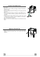
Air outlet – Recirculation Version • Insert the Connector extensions 14.1 into the side of the Connector 15. • Insert the Connector 15 into the Support bracket 7.3 and fix it with the screws. • Fasten the Support bracket 7.3, fixing it to the upper part with the Screws. • Make sure that the Connector extensions outlet 14.1 is in correspondence with the Chimney openings both horizontally and vertically.
Fitting the Panel and Fixing the Hood Canopy Before fixing the Hood Canopy to the Frame: • Remove the Grease filters from the Hood Canopy; • Remove any Activated charcoal filters. • Working from below, fix the Hood canopy to the Frame provided, using the 4 screws 12f (M6 x 10) provided. • Then hook the upper part of the Panel 3, adjusted to size, to the rubber supports in the upper part and in the lower part of the Frame.
USE T1 T2 T3 L Control panel BUTTON LED FUNCTIONS T1 Speed On Turns the Motor on at Speed one. Turns the Motor off. T2 Speed On Turns the Motor on at Speed two. T3 Speed Fixed When pressed briefly, turns the Motor on at Speed three. Flashing Pressed for 2 Seconds. Activates Speed four with a timer set to 10 minutes, after which it returns to the speed that was set previously. Suitable to deal with maximum levels of cooking fumes. L Light Turns the Lighting System on and off.
MAINTENANCE Grease filters CLEANING METAL SELF- SUPPORTING GREASE FILTERS • The filters must be cleaned every 2 months of operation, or more frequently for particularly heavy usage, and can be washed in a dishwasher. • Remove the filters one at a time by pushing them towards the back of the group and pulling down at the same time. • Wash the filters, taking care not to bend them. Allow them to dry before refitting. • When refitting the filters, make sure that the handle is visible on the outside.
OHJEET JA SUOSITUKSET Nämä käyttöohjeet koskevat useita tuuletintyyppejä. On mahdollista, että teksti käsittelee yksityiskohtia, jotka eivät kuulu valitsemaanne tuulettimeen. ASENNUS • Valmistaja ei vastaa virheellisestä tai huolimattomasta asennuksesta aiheutuvista vahingoista • Pienin sallittu turvaetäisyys liesitason ja liesikuvun välillä on 650 mm (jotkut mallit voidaan asentaa alemmas, katso mittoja ja asennusta koskevia kappaleita).
MITAT JA OSAT Osat Viite Lkm Tuotteen osat 1 1 Liesituulettimen runko, johon kuuluu: Kytkimet, valo, suodattimet 2 1 Teleskooppihormi, jossa on: 2.1 1 Ylähormi 2.2 1 Alahormi 3 1 Teleskooppitpaneeli, johon kuuluu: 3.1 1 Yläpaneeli 3.2 1 Alapaneeli 9 1 Sovituslaippa ø 150-120 mm 10a 1 Venttiilillä varustettu laippa ø 150 mm 10b 1 Suurennusrengas ø 120-125 mm 14.
Mitat Min. Min.
ASENNUS Katon/hyllyn poraaminen ja kehikon kiinnitys KATON/HYLLYN PORAAMINEN • Merkitse luotilangan avulla keittotason keskipiste kattoon/hyllyyn. • Aseta kattoon/hyllyyn toimitettu liesituulettimen malline 21 siten, että keskipiste tulee kohdalleen ja että keittotason ja mallineen sivut ovat samalla kohdalla. • Merkitse mallineen reikien keskipisteet. • Poraa reiät seuraavalla tavalla: • Massiivibetonikatto: käytettyjen betonimuuriankkurien mukaan.
Telineen/hormin kiinnitys Jos telineen korkeutta halutaan säätää, se tehdään seuraavalla tavalla: • Ruuvaa auki edessä näkyvät ruuvit, jotka yhdistävät kaksi etuosaa. • Säädä teline halutulle korkeudelle ja ruuvaa irrottamasi ruuvit takaisin. Muista laittaa 2 ruuvia paneeliryhmän lähelle. • Nosta teline ylös, aseta reiät ruuveihin ja työnnä vasteeseen saakka. • Kiristä kaksi ruuvia ja ruuvaa kiinni myös kaksi muuta toimitettua ruuvia. • Ota teleskooppihormin kiinnitystuki 7.
Suodatusversion ilman ulostulo • • • • Työnnä liitoksen jatkeet 14.1 sivuilta liitokseen 15. Aseta liitos 15 tukeen 7.3 ja kiinnitä se ruuveilla. Kiinnitä tuki 7.3 ruuveilla yläosaan. Varmista, että liitoksen jatkeet 14.1 tulevat ulos hormin aukkojen kohdalla sekä vaaka- että pystysuunnassa. • Liitä liitos 15 liesituulettimen ulostuloon jäykällä putkella tai letkulla, ø 150 mm, jonka valitsee asentaja. • Varmista, että aktiivihiilihajusuodatin on paikallaan. 12c 7.3 14.1 15 12e 7.
Paneelin asennus ja liesituulettimen rungon kiinnittäminen Ennen liesituulettimen rungon sijoittamista telineeseen: • Poista liesituulettimen rungosta rasvasuodattimet. • Poista mahdolliset aktiivihiilihajusuodattimet. • Kiinnitä sitten liesituulettimen runko alapuolelta valmiiseen telineeseen 4 toimitetulla ruuvilla 12f (M6 x 10). • Kiinnitä sitten paneelin 3 mittojen mukaan säädetty yläosa telineen ylä- ja alaosassa oleviin kumitukiin.
KÄYTTÖ T1 T2 T3 L Käyttöpaneeli PAINIKE MERKKIVALO TOIMINNOT T1 Nopeus Palaa Käynnistää moottorin ensimmäisellä nopeudella. T2 Nopeus Palaa Käynnistää moottorin toisella nopeudella. T3 Nopeus Kiinteä Lyhyt painallus käynnistää moottorin kolmannella nopeudella. Vilkkuva Kun painiketta painetaan 2 sekunnin ajan. Sammuttaa moottorin. Aktivoi neljännen nopeuden, joka toimii 10 minuuttia. Ajastetun ajan päätyttyä nopeus palaa asetettuun arvoon. Soveltuu käytettäväksi kun savua on paljon.
HUOLTO Rasvasuodattimet ITSEKANNATTAVIEN METALLISTEN RASVASUODATTIMIEN PUHDISTUS • Voidaan pestä myös astianpesukoneessa. Pesu on tarpeen noin 2 kuukauden käytön jälkeen tai useammin, jos laitetta käytetään paljon. • Irrota suodattimet yksi kerrallaan työntämällä niitä taaksepäin ja vetämällä samalla alaspäin. • Pese suodattimet. Vältä niiden taivuttamista. Anna suodattimien kuivua ennen niiden paikalleen asettamista. • Asenna ne paikalleen ja pidä kahva näkyvissä ulkopuolella.
991.0263.