CEILING FAN OWNER'S MANUAL READ AND SAVE THESE INSTRUCTIONS MODEL: 52-417-3SV-SN 52-417-3WA-13 FAN RATING AC 120V.
1. TOOLS AND MATERIALS REQUIRED Philips screw driver Blade screw driver 11 mm wrench Step ladder Wire cutters 2. PACKAGE CONTENTS Unpack your fan and check the contents. You should have the following items; a. b. c. d. e. f. g. h. i. j. k. Set of blades assembly (3) Blade support plates (3) Hanger bracket Canopy Downrod Coupling cover Fan motor assembly Mounting plate Light kit Glass shade Transmitter+holder+2 mounting screws l. Receiver+6 wire nuts m. 100W halogen bulb n.
. SAFETY RULES 1. To reduce the risk of electric shock, insure electricity has been turned off at the circuit breaker or fuse box before beginning. 9. To avoid personal injury or damage to the fan and other items, be cautious when working around or cleaning the fan. 2. All wiring must be in accordance with the National Electrical Code and local electrical codes. Electrical installation should be performed by a qualified licensed electrician. 10.
. MOUNTING OPTIONS If there isn't an existing CUL listed mounting box, then read the following instructions. Disconnect the power by removing fuses or turning off circuit breakers. Outlet box Secure the outlet box directly to the building structure. Use appropriate fasteners and building materials. The outlet box and its support must be able to fully support the moving weight of the fan (at least 50 lbs). Do not use plastic outlet boxes.
. HANGING THE FAN REMEMBER to turn off the power. Follow the steps below to hang your fan properly. CUL Listed electrical box NOTE: This ceiling fan is supplied with two types of hanging assemblies; the standard ceiling installation using the downrod with ball and socket mounting and the "close-to-ceiling" installation. The "close-to-ceiling" installation is recommended in rooms with less than 8-feet ceilings or in areas where additional space is desired from the floor to the fan blades.
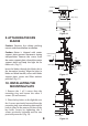
CLOSE-TO-CEILING INSTALLATION 1. Pass the 120-volt supply wires through the center hole in the ceiling hanger bracket as shown in Fig. 5. Canopy Figure 8 2. Remove the decorative canopy cover from the canopy. (Fig. 8) 3. Secure the hanger bracket to the ceiling outlet box with the screws and washers provided with your outlet box. Decorative canopy cover Screw and lockwasher (3 of 6 places) Canopy 4. Remove three of the six screws and lock washers (every other one) from the collar of top motor. (Fig.
6. INSTALLATION OF SAFETY SUPPORT An additional safety support is provided to prevent the fan from falling. Secure the safety cable to the ceiling joist with screw and washer, as illustrated in Figure 11. Hanger bracket Safety cable Figure 11 7. MAKE THE ELECTRIC CONNECTIONS Code switch WARNING: To avoid possible electrical shock, be sure electricity is turned off at the main fuse box before wiring.
Step 3. (Figure 14) Receiver to House Supply Wires Electrical Connections: Connect the black (hot) wire from the ceiling to the black wire marked "AC in L" from the receiver. Connect the white(neutral) wire from the ceiling to the white wire marked "AC in N" from the Receiver. Secure the wire connections with the plastic wire nuts provided.
Outlet box Screws Hanger bracket Ceiling canopy Figure 16 9. ATTACHING THE FAN BLADES Caution: Remove the rubber packing mounts and discard before installation. Caution: Motor is shipped with motor support plate prevent movement during transportation. Remove the screws from the motor support plate, discard the motor support plate and keep the light kit for future use . (Fig. 17) Rubber packing mounts Slot Motor support plate Insert the blades through the blade slot in the decorative housing.
11. INSTALLING THE LIGHT KIT NOTE: Before starting installation, disconnect the power by turning off the circuit breaker or removing the fuse at fuse box. Turning power off using the fan switch is not sufficient to prevent electric shock. Step 1. Remove the 1 of 3 screws from the mounting plate and keep it for future use. Loosen the other 2 screws (Do not remove). Connection plugs Step 2. Raise and hold the light kit close to the mounting plate and proceed to do the wire connections.
14. OPERATING INSTRUCTIONS MED HI Restore power to ceiling fan and test for proper operation. LOW OFF A. HI, MED, and LOW buttons: These three buttons are used to set the fan speed as follows: HI= high speed Med= medium speed Low= low speed B. OFF button: This button turns the fan off. C. button: This button controls the light. Press and release the button to turn the light ON or OFF. Press and hold the button to set the desired brightness.
15. TROUBLESHOOTING Problem Solution Fan will not start. 1. Check circuit fuses or breakers. 2. Check line wire connections to the fan and switch wire connections in the switch housing. CAUTION: Make sure main power is off. 3. Check to make sure the dip switches from the transmitter and receiver are set to the same frequency. Fan sounds noisy. 1. Make sure all motor housing screws are snug. 2. Make sure the screws that attach the fan blade bracket to the motor hub is tight. 3.