
Instruction Manual


Unpacking Your T-Glide Fence System
While unpacking your saw, verify that you have all the components shown below for your specic fence
system. The T-Glide Fence System – Professional Series is available in either a 52” system or a 36” system. The
components pictured below are from the 52” system, although the components from the 36” system are similar.
front tube
front rail
rear rail
extension table
installation instructions poster
owner’s manual
SawStop
®
OWNER’S MANUAL
T-Glide
TM
Fence System-
Professional Series
(four for 52” system,
two for 36” system)
angle bracket
fence handle
T-Glide table
hardware pack
18
Countersunk Socket
Head Bolts, M8 x 25 (6)
Washers,
M8.5 x 23 (6)
19
Lock Washers,
M8 (6)
20
Philips Head Screws,
M4 x 16 (12)
17
Foot,
(2)
13
Hex Head Bolts,
M10 x 45 (4)
15
Hex Nuts,
M8 (8)
14
Nylon Lock Nuts,
M10 (4)
16
T-Glide 52” Table Hardware Pack
T-Glide rails
hardware pack
T-Glide Rails Hardware Pack
1
Countersunk Socket Head Bolts,
M8 x 25 (8)
Lock Washers,
M8 (8)
3
Hex Nuts,
M8 (8)
4
Hex Head Screws with Attached
Washers, M8 x 16 (9)
6
Washers,
M8.5 x 23 (8)
2
Countersunk Socket
Head Screws, M8 x 16 (4)
5
SawStop
T-Glide fence
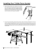
Assembling Your T-Glide Fence System
SawStop Service Department
503-682-6222
www.sawstop.com
Before assembling your T-Glide fence system,
make sure that you have all the necessary
components identified on page 1 in the Owner’s
Manual, including the two hardware packs. Call the
SawStop Service Department at 503-682-6222 if
any components are missing. You will also need the
following tools to complete the fence installation:
1. a 5 mm hex key
2. a 13 mm wrench
3. two 17 mm wrenches (or adjustable wrenches)
4. a Phillips head screwdriver
5. a level or straight-edge
Note: The drawings in the installation poster
illustrate the T-Glide rails and extension table for
the 52” system. The instructions for assembling
and using the 36” system are the same.
1
2
3
4
5
6
7
8
9
10
11
Flip to
Other Side
© SawStop, LLC
TM
1
0
15
30
SawStop
10” Contractor Sa
w
1
2
3
4
SawStop
System Statu
s Codes
S
t
a
tus
R
ed
G
r
n
¯
¯
¯
W
et
W
oo
d
Ove
rloa
d Due
T
o
Duri
ng
B
y
p
ass
Con
t
a
c
t
Detect
ed
Duri
ng S
t
a
n
d
b
y
Con
t
a
ct Det
ect
ed
Brak
e
Ad
just
P
osit
io
n of
Doo
rs
Close
Acces
s
Ke
y
T
o
“O
n
”
T
ur
n
Ca
rt
r
idge
T
o
“O
f
f”
T
urn
S
t
a
r
t
Switc
h
Byp
a
s
s Mo
de
O
n
Coa
s
tin
g
Down
Rep
la
c
e Ca
r
t
r
i
dg
e
Sys
tem
Rea
dy
Syst
em I
nitial
izing
•
•
•
• •
•
¯
¯
¯
¯
¯
¯
• •
•
•
•
•
¯
¯
¯
•
• •
•
•
•
• •
•
•
• •
•
•
•
•
•
•
•
•
•
• •
•
¯
¯
¯
•
•
•
•
• •
0
15
30
45
SawStop
10
” Contractor Saw
5
M
a
de
i
n
T
a
i
wa
n
S
a
wS
t
op
,
L
LC
w
w
w
.
s
a
w
s
t
o
p
.c
o
m
T
C
P
10
¨ Con
tract
or Saw
S
awS
top
®
Mo
de
l
N
o
.
CN
S 17
5
Se
r
i
a
l No
. C
07
4
0
12345
E
l
e
c
t
r
i
c
a
l /
El
e
c
t
r
i
cid
ad
/
Él
e
c
t
ricit
é
1
15/2
30
V
ol
t
s
,
6
0 Hz
1
5
/7.5
A
mp
s
1 Ph
as
e
1.75
H
P
350
0 RPM
®
c
US
1
7
5
3
7
0
M
o
vi
ng
b
el
t
s and
p
a
r
ts
c
a
n p
in
ch
,
cut
o
r c
r
us
h.
D
o not o
p
e
r
a
t
e
w
i
t
h
b
elt
gu
a
r
d o
p
en.
Ma
de in
T
aiwa
n
Saw
S
t
o
p
,
L
L
C
w
w
w
.
s
a
w
s
t
o
p
.
c
o
m
TC
P
1
0
¨
Cont
r
acto
r S
a
w
S
awStop
®
M
o
del N
o
. CN
S 1
75
Se
ria
l No
. C0
74
0
12
34
5
Ele
c
t
rica
l /
El
ec
t
ric
idad / É
le
c
t
rici
t
é
1
1
5
/
2
3
0
V
o
lt
s
, 6
0
H
z
15
/
7.
5
A
mp
s
1
Phas
e
1.
7
5
H
P
35
0
0
R
PM
®
c
U
S
1
753
7
0
M
o
ving
b
elt
s
and pa
r
ts
c
an pin
c
h
,
c
ut or
c
r
u
s
h
.
D
o
n
ot o
p
e
r
a
t
e wi
th
b
el
t g
ua
r
d o
p
en.
1
2
3
4
1
S
awS
to
p
,
the
S
aw
Sto
p
b
la
de
l
og
o,
a
nd
the
c
on
figur
a
ti
o
n
o
f
t
h
is
pro
du
ct
a
re
ei
t
he
r
r
e
gi
s
te
re
d
t
r
ad
em
a
rks
or
tr
ad
emark
s
o
f
S
aw
St
op,
LLC.
S
of
tw
a
r
e
c
op
y
r
ight
2
0
03
-2
006
by
S
awSto
p,
L
LC
.
A
l
l
r
i
g
hts
r
e
s
e
rve
d
.
P
ro
t
ec
ted
b
y
o
ne
or
m
o
re
of
t
h
e
f
ol
l
o
w
i
n
g
U
.S.
p
ate
nts
68
13
983,
6
82
69
8
8,
6
85
7345
,
68
7
741
0,
6880
440
,
6
920
81
4
,
694
51
48,
6
94
5149
,
69
5
760
1,
6
99
4
0
04
,
69
9
7
09
0,
70
00
51
4
,
7
02
4975
,
70
5
541
7,
7077
039
,
7
098
80
0
,
710
04
83,
7
13
7326
,
71
7
187
9,
7
19
7
9
69
,
72
1
0
38
3,
72
25
71
2
,
7
22
8772
,
7
231
8
5
6
and
T
a
i
wa
n
p
ate
n
t
14
3466.
A
ddi
ti
o
na
l
U
.S
.
an
d
fo
re
i
gn
pa
tents
p
e
nd
ing.
!
W
ARN
I
NG
D
o
n
ot
re
m
o
ve
th
e
du
st
sh
r
ou
d
b
ec
au
s
e
th
e
bla
de
wi
ll
be
e
x
p
ose
d.
I
f
yo
u
co
nt
a
c
t
th
e
bla
de
un
d
er
th
e
ta
b
le,
th
e
b
la
d
e
m
a
y
r
etra
ct
to
w
ar
d
you
an
d
c
au
s
e
a
se
v
ere
in
jur
y
.
13
14
15
16
17
front rail
level the top of
the front rail with
the lower edge
of the bevel
straight-edge
rear rail
straight-edge
support
leg
• Locate the front rail, the rear rail, and theT-Glide rails hardware
pack.All of the hardware needed to install the rails is located on
theT-Glide rails hardware pack and is shipped in the T-Glide
fence box. In order to easily identify the hardware used in each
of the following steps, the different pieces of hardware are
numbered on the hardware pack and in the figures.
•Align the front rail (the larger of the two rails) with the front edge
of the table top so the cut-outs at the top of the rail are centered
on the miter gauge slots in the table and so the holes in the rail
align with the holes along the front edge of the table and
extension wings. Remove six M8 x 25 countersunk socket
head bolts from theT-Glide rails hardware pack and insert
one through each of the holes in the rail and table.
1
• Place an M8.5 x 23 washer and an M8 lock washer
on the back of each of the six M8 x 25 countersunk
socket head bolts , and then thread an M8 hex nut on
each bolt. Hand tighten the nuts; do not fully tighten them.
2 3
1
4
•The holes in the front edge of the table and extension wings are
slightly larger than the bolts they receive to allow you to level the
front rail and extension wings to the table top.Align the top of
the front rail with the lower edge of the bevel on the front edge
of the table top. Use a 5 mm hex key and a 13 mm wrench to
fully tighten the nuts on the back of the four bolts that extend
through the table top. Do not tighten the nuts on the bolts that
extend through the extension wings.
bevel
tighten
level the extension
wing and tighten the
nut on this bolt
• Use a straight-edge to level the front edge of the left extension
wing to the cast iron table top.You may have to pull up or push
down on the outer edge of the extension wing to level it. Once
the front edge of the left extension wing is level, use a 5 mm hex
key and a 13 mm wrench to fully tighten the nut on the bolt that
mounts the left extension wing to the front rail. Repeat this
process to level the front edge of the right extension wing.
•Align the rear rail (the smaller of the two rails) with the rear
edge of the table top so the cut-outs at the top of the rail are
centered on the miter gauge slots in the table and so the holes
in the rail align with the holes along the back edge of the table
and extension wings. Notice that the holes in the table are
threaded but the holes in the extension wings are not. Remove
four M8 x 16 countersunk socket head screws from the
T-Glide rails hardware pack and thread one through each of the
holes in the rail and into the threaded holes in the table.
Tighten the four screws using a 5 mm hex key.
5
1
•Take two M8 x 25 countersunk socket head bolts and insert
one through each hole in each extension wing. Place an
M8.5 x 23 washer and an M8 lock washer on the
back of each bolt and then thread an M8 hex nut on
each bolt. Hand tighten the nuts; do not fully tighten them.
1
2
3
4
• Use a straight-edge to level the rear edge of the left extension
wing to the cast iron table top.You may have to pull up or push
down on the outer edge of the extension wing to level it. Once
the rear edge of the left extension wing is level, use a 5 mm hex
key and a 13 mm wrench to fully tighten the nut on the bolt that
mounts the left extension wing to the rear rail. Repeat this
process to level the rear edge of the right extension wing.
level the extension
wing and tighten the
nut on this bolt
• Once the rails are in place you can mount the extension table to
the rails, but first you must mount the support leg or legs to the
extension table.The extension table for the 36” fence system has
one support leg and the extension table for the 52” fence system
has two. Locate the support legs, the angle brackets, and the
T-Glide table hardware pack. Begin by installing the adjustable
foot in the bottom of each support leg.Thread an M8 nut onto
the threaded shaft of the foot as close to the rubber base as
possible, and then thread the foot into the bottom of the support
leg as far as possible.
14
13
• Each support leg is mounted to the underside of the extension
table using two angle brackets.Align the two holes in the
support leg to the two holes in the brackets. Put one of the
M10 x 45 hex head bolts through each hole in the leg and
brackets.Thread an M10 nylon lock nut on each bolt and
tighten with a 17 mm wrench.You will need to hold the head of
the hex bolt with another 17 mm wrench to tighten the lock nut.
Do not fully tighten the nuts; leave them just loose enough to be
able to move the brackets.
16
15
angle bracket
• Mount the angle brackets to the underside of the extension
table using three M4 x 16 Phillips head screws per bracket.
The underside of the extension table is pre-drilled to receive the
screws. Be careful not to overtighten the screws because you
may strip the threads in the wood. Once all the brackets
have been mounted to the table, fully tighten the
M10 nylon lock nuts that secure the legs to the brackets.
17
T-Glide Rails Hardware Pack
1
Countersunk Socket Head Bolts,
M8 x 25 (8)
Lock Washers,
M8 (8)
3
Hex Nuts,
M8 (8)
4
Hex Head Screws withAttached
Washers, M8 x 16 (9)
6
Washers,
M8.5 x 23 (8)
2
Countersunk Socket
Head Screws, M8 x 16 (4)
5
18
Countersunk Socket
Head Bolts, M8 x 25 (6)
Washers,
M8.5 x 23 (6)
19
Lock Washers,
M8 (6)
20
Philips Head Screws,
M4 x 16 (12)
17
Foot,
(2)
13
Hex Head Bolts,
M10 x 45 (4)
15
Hex Nuts,
M8 (8)
14
Nylon Lock Nuts,
M10 (4)
16
T-Glide 52”Table Hardware Pack
support leg
(two for 52” system,
one for 36” system)
SawStop T-Glide Fence System - Professional Series 1