
Installation guide

WAFER-945GSE 3.5” Motherboard
Page 82
Chapter 3.
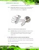
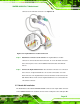
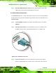
Step 2: Insert the cable connectors. Insert one connector into each serial port box
headers. See Figure 5-13. A key on the front of the cable connectors ensures
the connector can only be installed in one direction.
Figure 5-13: Dual RS-232 Cable Installation
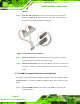
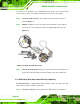
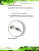
Step 3: Secure the connectors. Both single RS-232 connectors have two retention
screws that must be secured to a chassis or bracket.
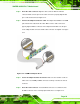
Step 4: Connect the serial device. Once the single RS-232 connectors are connected
to a chassis or bracket, a serial communications device can be connected to the
system. Step 0:
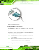
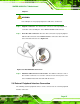
5.7.5 4-COM Port Adapter Board Connection (Optional)
An optional, separately purchased 4-COM port adapter board may be shipped with the
WAFER-945GSE. To install the 4-COM Port Adapter Board, please follow the steps
below.
Step 1: Locate the COM connector. The locations of the COM port connectors are
shown in Chapter 4.