
Installation guide

WAFER-945GSE 3.5” Motherboard
Page 70
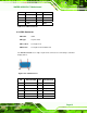
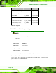
Description Label Type
AT Power Mode Setting ATXCTL1 2-pin header
CF Card Setting JCF1 2-pin header
Clear CMOS J_CMOS1 3-pin header
COM2 Mode Setting JP1 6-pin header
LVDS1 Panel Resolution J_LCD_TYPE1 8-pin header
LVDS1 Voltage Select J_VLVDS1 3-pin header
Table 5-1: Jumpers
5.5.1 AT Power Select Jumper Settings
NOTE:
The AT Power Select Jumper is the same as the ATX Enable
connector.
Jumper Label: ATXCTl1
Jumper Type:
3-pin header
Jumper Settings: See
782HTable 5-2
Jumper Location:
See
783HFigure 5-4
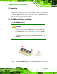
The AT Power Select jumper specifies the systems power mode as AT or ATX. Use a
jumper cap to short pin 1 - pin 2 on the ATXCTL1 connector to enable the AT Power mode
on the system. In the ATX mode use the PS_ON- and 5VSB cable. AT Power Select
jumper settings are shown in
784HTable 5-2.