
Operating instructions

INSTALLING THE AT10.1
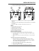
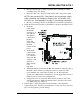
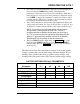
1.10. WIRING TO THE REMOTE ALARM CONTACTS
Built-in Summary (Common) Alarm Relay (standard)
The AT10.1 Main
Control PC Board (A1)
is equipped with a
"common" Summary
Alarm relay. This relay
contact transfers when
any one or more of the
standard AT10.1
alarms exist.
See Section 2.2.7 for a
description of the alarm
functions. One form-C
alarm contacts are
provided, and
accessible via terminal
block (TB3), as show
in the figure on the
right.
Follow the procedure
below to wire a remote
annunciator to this
contact.
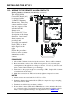
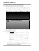
PROCEDURE
1. Allow 30in / 762mm of wire inside the enclosure. Excess will be trimmed.
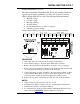
2. Route annunciator wires to the AT10.1 front panel door by following the
existing harness through the door hinge as shown. Use two (2) wire ties and
allow a 4-6in / 102-153mm loop for the hinge.
3. Trim wires to the proper length for connecting to TB3. Strip 0.25in / 6.4mm
of insulation from the wires.
4. Make the connections at TB3, and securely tighten compression screws.
NOTES
1. Alarm contacts are rated at 0.5A / 125 Vac or Vdc.
2. Summary Alarm relay terminal block (TB3) is compression type, accepting
wire sizes #22-14 AWG.
3. Terminals are labeled in non-alarm condition.
4. If user alarm contacts (TB3 and/or TB4A/B) are to drive inductive dc loads
(e.g. a larger dc relay) an external protective diode must be applied at the dc
relay to avoid equipment damage. See Application Note (JD5011-00).
18