
Operating instructions


SERVICING THE AT10.1
46
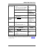
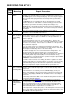
Error
Code
Meaning Repair Procedure
E 04
internal memory
failure
Any parameters that you set, such as Float or Equalize voltage, are saved
internally. The internal memory is tested on startup. If the memory test
fails, E 04 appears on the front panel display. The error may also appear
if the controller was trying to write to the memory while a power failure
occured.
If an E 04 appears, try restarting the AT10.1 by turning the ac and dc
breakers off, then on. If the AT10.1 restarts normally, you must reenter
any changes you made to the factory settings (float voltage, etc.).
If E 04 appears repeatedly, the internal memory has been damaged. You
must replace the control circuit board. See Section 3.6 for parts ordering
information.
E 05
not used
This error code was formerly used to indicate a reverse battery
connection. It is not available in the AT10.1.
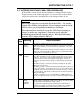
E 06
defective R4 or
R14, or remote
sense wiring
failure
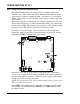
Locate R4 mounted on TB5, on the back of the front panel. Remove the
resistor and measure its value with an Ohmmeter (see table 3-1 for the
correct value). If the resistor is not within 1% of the specified value, it
must be replaced.
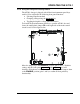
Locate R14 inside the enclosure, connected to TB1(-). Remove the
lugged end and measure the resistor's value with an Ohmmeter (see table
3-1 for the correct value). If the resistor is not within 1% of the specified
value, it must be replaced.
If you are using remote sense wiring from the battery to the AT10.1, the
wiring may have failed. The usual failure is an open circuit; a short circuit
will usually be indicated by smoke or fire in the wiring.
The AT10.1 displays the error code if it detects this wiring failure. You
should respond to this problem quickly to be sure that the AT10.1
regulates the output voltage properly. Wire an annunciator (e.g. buzzer) to
the summary alarm relay contact (TB3) for remote indication of any
charger problem, or monitor the AT10.1 operation using the optional DNP-
3/MODBUS communications board.
If a failure exists in remote sense wiring, the AT10.1 regulates its output
voltage locally until you correct the problem, see Section 1.9. The locally
controlled voltage may not reflect the true requirements of the battery.
When you complete the repair, restart the AT10.1 per Section 2.1.
E 07
dc breaker
open, or internal
dc wiring failure
If the dc breaker is open, open the ac breaker, then reclose the dc and ac
breakers. If the dc breaker trips again, see the troubleshooting chart in
Section 3.4.
If the dc breaker is closed, but you have an E 07 display, check your
battery. If the battery is disconnected, and you then disconnect the load,
the AT01.1 may display an E 07 code. Restart the AT10.1 according to
Section 2.1.
If the battery and load are OK, see the troubleshooting chart in Section 3.4
for help in locating the problem.
E 08
defective
temperature
compensation
probe
See Application Note (JD5003-00) for more detailed user instructions.
If a temperature compensation probe is connected to the AT10.1, the
control circuit detects the probe on startup, and uses the temperature
measured by the probe to control the output voltage of the AT10.1. To
understand temperature compensation, see Section 1.11.
If the temperature compensation probe, or the wiring that connects it to the
AT10.1, fails during normal operation, the AT10.1 detects the failure, and
shows E 08 on the front panel meter.