OPERATOR'S MANUAL MAGNUM III MODEL MAG FROM SERIAL NUMBER 70001 TO 79999 PART 03034
WARNING FAILURE TO FOLLOW SAFE OPERATING PRACTICES MAY RESULT IN SERIOUS INJURY. * Keep all shields in place, especially the grass discharge chute. * Before performing any maintenance or service, stop the machine and remove the spark plug wire and ignition key. * If a mechanism becomes clogged, stop the engine before cleaning. * Keep hands, feet and clothing away from power-driven parts. * Read this manual completely as well as other manuals that came with your mower.
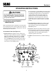
Section 1 GENERAL INFORMATION For pictorial clarity, some illustrations and Figures in this manual may show shields, guards or plates open or removed. Under no circumstances should your mower be operated without these devices in place. 1.1 INTRODUCTION Your mower was built to highest standards in the industry. However, the prolonged life and maximum efficiency of your mower depend on you following the operating, maintenance and adjustment instructions in this manual.
Section 2 SAFETY INFORMATION 2.1 INTRODUCTION Your mower is only as safe as the operator. Carelessness or operator error may result in serious bodily injury or death. Hazard control and accident prevention are dependent upon the awareness, concern, prudence, and proper training of the personnel involved in the operation, transport, maintenance and storage of the equipment. Make sure every operator is properly trained and thoroughly familiar with all the controls before operating the mower.
Section 2 6. Prolonged exposure to loud noise can cause hearing impairment or loss. Operator hearing protection is recommended, particularly for continuous operation of the mower. Wear suitable hearing protection. 2.4 OPERATION CONSIDERATIONS 7. Keep the machine and attachments in good operating condition. Keep all shields and safety devices in place. If a shield, safety device or decal is defective or damaged, repair or replace it before operating the machine. 2.
Section 2 9. DO NOT turn sharply. Use care when backing up. 2.5 MAINTENANCE CONSIDERATIONS 10.Use counterweights or wheel weights when suggested in this manual. 1. Never make adjustments to the machine with the engine running unless specifically instructed to do so. If the engine is running, keep hands, feet, and clothing away from moving parts. 11.Watch for traffic when crossing roads or operating near roadways . 12.Mow only in daylight or good artificial light. 2.
Section 2 2.
Section 3 3.1 ENGINE SPECIFICATIONS General Type ............................................................................. Heavy Duty Industrial/Commercial Diesel Brand ......................................................................................... Kubota 28 HP Super 5 Series, Electric Start Model ......................................................................................... D1105-B Horsepower ................................................................................
Section 3 3.3 TRACTOR (CONT'D) Seat ............................................................................................ Milsco Seat With Adjustment Lever For Forward and Back Movement Travel Speed: Forward ................................................................................ 0 - 8 MPH Infinitely Variable Reverse ................................................................................. 0 - 4.3 MPH Infinitely Variable 3.4 CUTTER DECK No. of Blades .................................
Section 4 OPERATING INSTRUCTIONS Do not hold the key in the START position longer than 15 seconds. If the engine does not start, return the key to the OFF position for at least 60 seconds before a restart attempt is made. Prolonged cranking can damage the starter motor and shorten battery life. Release the key when the engine starts and it will automatically return to the run position. To stop the engine, rotate the key counter-clockwise to the OFF position.
Section 4 5. Temperature Gauge: Indicates engine coolant temperatures. Green zone indicates proper working temperature. Red zone indicates engine over heating and the engine should be shut off immediately. Parking Brake Lever 6. Fuel Gauge: Indicates the amount of fuel in the fuel tank. 7. Engine Oil Pressure Indicator Light: Indicator will light if oil pressure drops below a safe operating pressure. Stop the engine immediately; determine the cause and correct the problem before continuing operation.
Section 4 4.2 SAFETY INTERLOCK SYSTEM 4.3 INITIAL RUN-IN PROCEDURES (First Day of Use or Approximately 10 Hours) This mower is equipped with a safety system that prevents the engine from starting unless the mower blade brake is disengaged and parking brake is engaged. The system also shuts the engine off if the operator's left foot is raised from the interlock pedal with the mower and parking brakes disengaged. 1. Check all belts for proper tension at 2, 4 and 8 hours; adjust as needed. 2.
Section 4 4.4 DIESEL ENGINE BREAK-IN The proper break-in of a new diesel engine can make a difference in the performance and life of the engine. Perform the following break-in procedure during the first 50 hours of operation: 1. A new engine should be operated with as near full load as possible. However, the engine must be allowed to reach an operating temperature before operating at full load conditions. 2. The engine oil should be checked twice daily.
Section 4 1. To travel forward, depress the right foot pedal at the toe. (See Figure 4-6). The further the pedal is depressed the faster the mower will travel forward. B. Seat Adjustment 1. Pull the handle on the left side of seat (Figure 4-5) and move the seat either forward or back. 2. Release the handle to lock the position.
Section 4 4. When traveling, the throttle control can be adjusted to increase or decrease travel speed. 3. Always operate the engine at full throttle to properly maintain cutting speeds. If the engine starts to lug down, reduce the forward speed to allow the engine to operate at maximum RPM. 5. Reduce speed when turning around trees, shrubs, etc. 4.9 HILLSIDE OPERATION 3. Check that all systems function correctly. IMPORTANT: Avoid high-speed turns on all surfaces.
Section 4 -IMPORTANTIf at all possible, do not engage the mower brake with engine running at high speed, since premature wear of the electric clutch will occur. Lower speed to near idle then engage the brake. CAUTION: The blade brake stops the blades from rotating. If the blades do not stop, contact your Scag Dealer. CAUTION: Remove the key from the ignition switch when leaving the mower unattended to inhibit children and inexperienced operators from starting the engine.
Section 4 -IMPORTANTDo not wash a hot or running engine. Use compressed air to clean the engine and the radiator fins. Cold water will damage the engine and/or radiator. 4. Keep the entire mower clean to inhibit serious heat damage to the engine or hydraulic oil circuit. 5. Recheck the cutter drive belts for proper tension, alignment and any signs of rubbing. Correct and adjust as necessary. 6. Fill the fuel tank with fresh, clean fuel at the end of every day of operation. 7. Check the tire pressure.
Section 4 4.15 TILTING THE MOWER DECK CAUTION: 1 2 3 4 Do not tilt the deck with the mower blades rotating. Engage the blade brake before tilting the deck. Bodily injury or damage to the mower or property could result. 1. Stop the traveling movement of the mower and engage the blade brake. 2. Use the deck tilt control switch on the instrument panel to raise the deck. 3. Before lowering the deck, observe that there are no objects under the deck.
Section 5 TROUBLESHOOTING CUTTING CONDITIONS CAUSE CONDITION Stringers - Occasional Blades of Uncut Grass CURE Low engine RPM Run engine at full 3600 RPM Ground speed too fast Slow speed to adjust for conditions Wet grass Cut grass after it has dried out Dull blades, incorrect sharpening Sharpen blades Deck plugged, grass accumulation Clean underside of deck Width of Deck Belts slipping Adjust belt tensions Dull, worn blades Sharpen blades Incorrect blade sharpening Sharpen blades Low engi
Section 5 TROUBLESHOOTING CAUSE CONDITION Uneven Cut on Flat Ground - Wavy High-Low Appearance, Scalloped Cut, or Rough Contour CURE Lift worn off of blade Replace blade Blade upside down Mount with cutting edge toward ground Deck plugged,grass accumulation Clean underside of deck Too much blade angle (deck pitch) Adjust pitch and level Deck mounted improperly See your authorized SCAG dealer Bent spindle area See your authorized SCAG dealer Dull blade Sharpen blade Uneven ground May need to
Section 5 TROUBLESHOOTING CAUSE CONDITION Scalping - Blades Hitting Dirt or Cutting Very Close to the Ground Width of Deck CURE Low tire pressures Check and adjust pressures Ground speed too fast Slow speed to adjust for conditions Cutting too low May need to reduce ground speed, raise cutting height, change direction of cut, and/or change pitch and level Rough terrain May need to reduce ground speed, raise cutting height, and/or change direction of cut Ground speed too fast Slow speed to adjus
Section 6 ADJUSTMENTS 6.2 FORWARD/REVERSE NEUTRAL ADJUSTMENT 6.1 PARKING BRAKE ADJUSTMENT The forward/reverse linkage should be adjusted whenever the mower will not stay stationary when the forward/reverse (right) foot pedal is placed in the neutral position. WARNING: Do not operate the mower if the parking brake is not operable. Possible severe injury could result. 1. Set the engine deck on jack stands so the wheels are free to rotate.
Section 6 -NOTEIf you turn the nut too much, you will compress the spring, making too much end play. Go to step 4. 4. If the drive wheels rotate in rearward travel direction, turn the adjustment bolt (Figure 6-1) clockwise until rotation stops. If the drive wheels rotate in the forward travel direction, turn the adjusting bolt counterclockwise until rotation stops. 5. Check the adjustment of the right foot pedal for full forward speed.
Section 6 3. After proper tension is obtained, tighten the two bolts and install the pump belt guard. Adjusting Bolt 6.6 PUMP DRIVE BELT ADJUSTMENT To adjust belt tension, turn the adjusting nut (Figure 6-1) until 1/2 inch deflection in belt is obtained with 10 pounds of pressure. See Engine Drive Belts, section 7.9 for checking method. 6.7 ELECTRIC CLUTCH DRIVE BELT ADJUSTMENT To adjust the belt tension, turn the adjusting nut (Figure 64) to obtain 1/2 inch belt deflection with 10 pounds of pressure.
Section 6 To level the deck, loosen the adjusting nut (Figure 6-8) and lift or lower the deck until the left side measurement equals the right side measurement. Tighten the adjusting nut. 6.10 BELT ALIGNMENT Belt alignment is important for proper performance of your Scag mower. If you experience frequent belt wear or breakage, see your authorized Scag service dealer for belt adjustment. 6.
Section 6 2. Turn the adjusting rods counter-clockwise to lower the front of the deck and clockwise to raise the front of the deck. When a difference of 1/4 inch from front to rear is obtained on left and right, tighten both jam nuts. Adjusting Nut Jam Nut Blade 1 2 3 4 Tape Measure Figure 6-11 Measuring Cutting Edge Height Adjusting Rod Loosen the two jam nuts on the gauge rod (See Figure 6-12). Slide the gauge rod to the proper setting on the height gauge. Tighten the jam nuts.
MAG-61, MAG-72 CUTTER DECK 3 1 2 1 2 3 4 1 4 5 3 2 38 4 74 28 7 12 16 25 71 70 11 10 26 20 10 14 9 19 29 68 25 13 24 22 67 73 13 15 24 24 69 12 72 23 32 5 8 9 39 74 35 16 17 18 27 65 21 31 16 33 35 37 24 68 34 6 64 36 41 32 24 40 58 53 12 2 42 16 12 54 64 16 43 44 41 62 55 32 63 53 61 56 60 53 41 58 2 57 45 59 54 54 58 47 2 46 48 49 55 44 55 50 56 56 41 51 52 390S0111 40
MAG-61, MAG-72 CUTTER DECK Ref. Part. No.
MAG-61, MAG-72 DECK SUPPORT 69 36 67 2 1 70 68 33 65 65 64 67 57 4 2 66 5 59 3 58 57 47 46 47 48 48 45 49 62 43 44 13 41 8 42 39 47 51 60 50 49 63 67 52 43 61 44 54 52 67 39 74 23 23 37 48 47 49 44 5 41 46 23 42 41 55 61 7 56 15 5 16 11 12 14 11 3 26 71 9 10 13 38 38 25 35 12 11 23 11 23 10 12 17 18 8 24 13 21 19 20 21 12 22 75 73 26 36 6 8 23 56 53 5 22 43 42 40 45 23 72 39 39 17 34 12 27 29 12 32 28 31 30 29 27 390S0112
MAG-61, MAG-72 CUTTER DECK SUPPORT Ref. Part No.
RIDER FRAME 60 61 6 8 1 7 2 38 54 9 49 50 4 48 3 51 53 5 10 52 57 4 46 41 46 11 48 45 58 44 47 10 46 59 13 12 43 42 15 14 55 36 35 17 16 18 56 3 33 37 41 18 34 38 19 40 32 20 31 39 30 29 16 28 27 22 26 25 24 23 21 390S0113 44
RIDER FRAME Ref. Part No. Number Description Ref. Part No.
ENGINE DECK 1 37 2 53 17 56 3 52 4 17 56 5 7 57 17 51 18 37 50 47 6 46 67 48 11 8 16 38 10 44 15 61 60 A 59 65 64 49 14 58 9 17 45 61 12 63 64 B 68 B 65 70 62 66 13 54 14 17 18 14 58 43 63 19 20 69 51 A 39 71 42 29 37 41 35 40 21 14 15 17 16 24 27 28 37 25 26 36 55 19 34 33 32 30 22 31 23 390S0114 46
ENGINE DECK Ref. Part No. Number Description Ref. Part No.
RADIATOR/OIL COOLER 29 4 1 27 2 31 3 7 2 6 5 28 30 8 9 11 10 24 23 26 23 25 24 11 20 16 2 19 18 13 14 12 15 16 17 21 22 390S0115 48
RADIATOR/OILCOOLER Ref. Part No. Number Description 1 2 3 4 5 6 7 8 9 10 11 12 13 14 15 16 17 18 19 20 21 22 23 24 25 26 27 28 29 30 31 481207 48136-06 45783 04019-03 * 422192 04003-12 481286 45784 45785 04001-06 422010 421992 04003-11 * * 04021-05 * 481302 481206 04041-07 04021-09 04040-14 04030-02 48576-03 481383-01 422194 04001-44 04001-59 04019-02 04021-08 Hose, Upper Radiator Clamp, Hose Shroud, Fan Serr. Fl.
MUFFLER AND AIR CLEANER 4 3 1 2 1 5 6 7 9 8 10 11 20 19 15 18 16 15 14 13 15 14 12 17 15 390S0116 50
MUFFLER AND AIR CLEANER Ref. Part No. Number Description 1 2 3 4 5 6 7 8 9 10 11 12 13 14 15 16 17 18 19 20 48136-08 481191 481333 04100-03 481192 421981 04030-03 04020-03 * 481340 04015-07 422029 04001-09 04003-12 04019-03 421983 481439 48633 422254 04011-08 Hose Clamp Hose, Air Intake Cap. Precleaner U-Bolt Air Cleaner Mounting Bracket, Air Cleaner Lockwasher, 5/16 Nut, Hex, 5/16-18 Gasket, Manifold Adapter, Manifold Capscrew, Socket Head, M8-1.
DECK DRIVE SYSTEM 31 27 28 23 18 19 20 37 36 51 25 22 35 21 23 30 34 27 28 33 44 49 29 26 46 38 50 9 32 45 50 17 47 41 42 5 46 48 24 16 39 4 24 3 15 43 40 2 14 8 11 1 13 12 10 9 8 7 6 390S0117 52
DECK DRIVE SYSTEM Ref. Part No. Number Description Ref. Part No.
PUMP AND FAN DRIVE SYSTEMS 14 8 12 7 7 8 15 11 10 7 9 8 16 7 1 2 4 8 5 17 3 11 6 48 8 7 17 3 47 29 34 46 35 18 20 45 49 24 22 PART OF ENGINE 23 36 13 21 25 50 4 37 38 49 28 39 7 19 27 8 26 31 7 8 32 30 33 40 44 21 42 7 43 41 10 390S0118 54
PUMP AND FAN DRIVE SYSTEMS Ref. Part No. Number Description Ref. Part No. Number Description 1 2 3 4 5 6 7 8 9 10 11 12 13 14 15 16 17 18 19 20 21 22 23 24 25 26 27 28 29 30 31 32 33 34 35 36 37 38 39 40 41 42 43 44 45 46 47 48 49 50 Belt, Fan Drive Upright, Fan Support - RH Base, Idler Pivot - Pump Rod, J-Hook Spacer, J Pull Rod Grease Fitting Taper Hub, .75 Bore Pulley, Pump, 5.94 O.D.
INSTRUMENT PANEL 4 3 2 1 29 27 6 7 31 30 9 33 8 28 9 10 12 11 12 11 5 21 20 12 11 9 19 12 9 13 11 14 15 25 20 21 20 19 32 16 16 20 26 21 29 9 12 25 18 24 11 18 17 15 19 20 21 22 23 390S0119 56
INSTRUMENT PANEL Ref. Page No.
WIRING HARNESS AND ELECTRICAL COMPONENTS 1 28 29 8 2 7 31 9 6 5 30 4 10 3 11 11 27 18 26 25 32 24 12 33 13 34 23 2 22 15 15 16 17 18 21 19 20 14 390S0120 58
WIRING HARNESS AND ELECTRICAL COMPONENTS Ref. Page No.
CUTTER BRAKE LINKAGE 1 7 6 2 2 3 5 4 9 8 14 17 6 10 12 11 35 29 14 11 38 13 14 15 18 16 24 36 39 40 25 22 21 25 40 13 41 16 27 41 19 24 11 27 30 37 23 26 20 11 39 40 25 31 21 21 34 25 14 28 40 21 32 33 14 390S0121 60
CUTTER BRAKE LINKAGE Ref. Part No.
PARKING BRAKE LINKAGE 1 28 27 6 2 17 16 29 3 16 8 4 18 14 6 34 24 30 20 15 5 16 6 14 11 13 22 23 6 21 6 5 19 12 10 8 35 9 3 16 31 7 4 32 8 6 7 24 21 26 20 25 20 12 22 23 24 62 MAG008 33 4 3
PARKING BRAKE LINKAGE Ref. Part No. Number Description 1 2 3 4 5 6 7 8 9 10 11 12 13 14 15 16 17 18 19 20 21 22 23 24 25 26 27 28 29 30 31 32 33 34 35 48093 45716 48114-04 04050-01 04020-05 04041-07 48464 04021-09 45782 04020-14 04004-23 04003-05 481474 04001-19 04017-17 04019-04 45781 04001-21 421338 04019-02 04001-59 44108 43032 0462-02 45705 04017-37 04019-03 04019-06 48544 43212 44124 45834 04001-51 45835 04003-03 Grip, Handle Lever, Brake Grease Fitting Retaining Ring, .
THROTTLE LINKAGE 1 2 32 3 15 34 23 28 28 9 37 10 7 26 27 7 35 5 6 8 30 11 29 4 12 38 30 17 13 18 27 33 26 18 17 25 31 23 16 14 19 39 36 20 23 21 19 24 21 22 390S0123 64
THROTTLE LINKAGE Ref. Part No. Number Description 1 2 3 4 5 6 7 8 9 10 11 12 13 14 15 16 17 18 19 20 21 22 23 24 25 26 27 28 29 30 31 32 33 34 35 36 37 38 39 04003-02 421776 04019-02 04001-13 46877 48114-05 48100-04 44115 04002-11 45822 04021-13 04041-10 481244 04004-26 04020-03 481189 04040-04 04001-10 04019-02 481314 04019-03 04001-39 04021-10 04001-59 421997 04021-09 48464 04040-04 04001-20 04020-14 481188 481092 481243 04001-51 04030-05 04001-125 43110 43212 04020-13 Carriage Bolt, 1/4-20 x .
FORWARD/REVERSE LINKAGE 1 2 3 4 5 10 16 1 3 4 2 6 4 10 7 8 9 22 15 17 24 12 13 21 11 20 18 19 12 14 390S0124 66
FORWARD/REVERSE LINKAGE Ref. Part No. Number Description 1 2 3 4 5 6 7 8 9 10 11 12 13 14 15 16 17 18 19 20 21 22 23 04021-09 48544 04041-07 04003-05 04004-22 45708 04021-08 04001-59 04003-04 04020-14 04019-03 43257 48463 48512 421148 48464 481102 04001-71 04030-06 04020-07 04010-11 04021-01 04040-15 Hex Locknut, Elastic Stop, 3/8-16 Ball Joint, 3/8-24 LH Thread Flatwasher, 3/8 (.391 x .938 x .
FUEL TANK AND LINES 27 8 3 28 5 31 23 6 29 2 7 24 30 1 9 25 4 16 10 26 23 15 9 16 16 17 16 15 14 15 16 16 18 20 16 15 11 13 16 22 16 14 19 16 21 15 390S0125 68
FUEL TANK AND LINES Ref. Part No. Number Description 1 2 3 4 5 6 7 8 9 10 11 12 13 14 15 16 17 18 19 20 21 22 23 24 25 26 27 28 29 30 31 46933 481313 481304 481312 04017-16 481298 45864 04020-01 48136-08 481296 481307 48030-08 04017-05 04019-02 481178 48136-05 481308 * * 04017-17 04019-03 04021-08 48059-03 481179 04017-04 422003 04030-01 481431 481432 48351-10 48502-04 Fuel Tank (Includes 2, 3, 4) Fitting, Return Line Sender Unit, Fuel Level (Includes Gasket and Screws) Fitting, Hose Serr. Fl.
HYDRAULIC CIRCUITS 1 2 3 2 4 5 30 2 6 28 7 2 25 16 29 8 13 26 6 17 10 31 2 6 11 12 6 13 6 24 9 27 13 14 15 23 6 17 16 22 18 21 19 20 390S0126 70
HYDRAULIC CIRCUITS Ref. Part No.
*DELAY MODULE TIMER *VOLTMETER BLK PINK FUSE HOLDER RED RED RED *FUEL GAUGE *WATER TEMPERATURE GAUGE BLK BLK RED G BLK G S ORN G BLK ORN GRN ORN ORN WHT ORN ORN PINK BLK *GLOW PLUG LIGHT ORN ORN BLK BLK BLK RED WHT *CLUTCH KILL CIRCUIT RELAY BLU WHT ORN/WHT B RED A B E D C A WHT E D C RED BLK PINK GRN ORN BLK GRN ORN *LOW OIL PRESSURE LIGHT I BLK LT.
REPLACEMENT DECALS AND INFORMATION DANGER WARNING ROTATING BLADES AND BELTS SPINNING BLADE KEEP HANDS, FEET & CLOTHING CLEAR KEEP ALL GUARDS IN PLACE SHUT OFF ENGINE & DISENGAGE BLADE CLUTCH BEFORE SERVICING CLEAR AREA OF DEBRIS BEFORE MOWING USE CAUTION IN DIRECTING DISCHARGE KEEP BYSTANDERS, CHILDREN & PETS AWAY READ INSTRUCTION MANUAL BEFORE OPERATING DO NOT OPERATE WITHOUT DISCHARGE CHUTE, MULCHING 481040 KIT, OR ENTIRE GRASS CATCHER INSTALLED KEEP CLEAR CONTACT CAN INJURE 48071 1 2 7a, 7b 10
GREASE FITTING LUBRICATION CHART LUBRICATION NO. OF LOCATION INTERVAL LUBRICANT PLACES 1. Cutter Drive Spindle 40 Hours/Weekly +Lithium MP White Grease 2125 1 2. Cutter Deck Spindles 40 Hours/Weekly +Lithium MP White Grease 2125 3 3. Caster Wheel Bearing 100 Hours/Bi-Monthly Chassis Grease 2 4. Caster Wheel Pivot 100 Hours/Bi-Monthly Chassis Grease 2 5. Electric Clutch Belt Idler Arm 100 Hours/Bi-Monthly Chassis Grease 1 6.
75
SPECIFICATIONS ENGINE General Type ............................................................................. Heavy Duty Industrial/Commercial Diesel Brand ......................................................................................... Kubota 28 HP Super 5 Series, Electric Start Model ......................................................................................... D1105-B Horsepower ................................................................................
TRACTOR (CONT'D) Seat ............................................................................................ Milsco Seat With Adjustment Lever For Forward and Back Movement Travel Speed: Forward ................................................................................ 0 - 8 MPH Infinitely Variable Reverse ................................................................................. 0 - 4.3 MPH Infinitely Variable CUTTER DECK No. of Blades ...................................................
! WARNING: If incorrectly used, this machine can cause severe injury. Those who use and maintain the machine should be trained in its proper use, warned of its dangers, and should read the entire manual before attempting to set up, operate, adjust or service the machine.
© 1996 SCAG POWER EQUIPMENT DIVISION OF METALCRAFT OF MAYVILLE, INC. PART NO.