E R FO G BE E IN R IN N VE CHAL R CO A NU A LT G M'S MA W BE TINRATOR LL RAOPE TA E D S OPREA IN THIS MANUAL CONTAINS THE OPERATING INSTRUCTIONS AND SAFETY INFORMATION FOR YOUR SCAG ACCESSORY. READING THIS MANUAL WILL PROVIDE YOU WITH MAINTENANCE AND ADJUSTMENT PROCEDURES TO KEEP YOUR ACCESSORY PERFORMING TO MAXIMUM EFFICIENCY. THE SPECIFIC MODELS THAT THIS BOOK COVERS ARE CONTAINED ON THE INSIDE COVER. BEFORE OPERATING YOUR MACHINE, PLEASE READ ALL THE INFORMATION ENCLOSED.
WARNING FAILURE TO FOLLOW SAFE OPERATING PRACTICES MAY RESULT IN SERIOUS INJURY. * Keep all safety shields in place. * Before performing any maintenance or service, stop the machine and remove the spark plug wire. * If a mechanism becomes clogged, stop the engine before cleaning. * Keep hands, feet and clothing away from power-driven parts. * Read this manual completely as well as the Operator's Manual that came with your mower. * Keep others off the tractor (only one person at a time).
2.1 SAFETY AND OPERATING INSTRUCTIONS 1.1 INTRODUCTION This manual has been prepared to provide the information you need to correctly assemble, operate, and maintain this grass catcher. Read it carefully and keep it for future reference. -NoteTo avoid personal injury, it is imperative that all safety instructions be observed. 1. Read this operator's manual and the operator's manual that is supplied with the machine this attachment is used on.
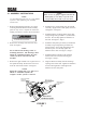
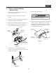
3.1 ASSEMBLY INSTRUCTIONS -NOTEUse the illustrated parts list as a part number reference when following the assembly instructions. 1. Remove all packaging materials. Lay out the mounting hardware and the catcher assembly parts for easy access. Prepare the work area making sure that it is a clean, safe environment. 4. Install the grass catcher pulley onto the spindle assembly. Apply loctite to both pulley setscrews and tighten. See Figure 1. 5.
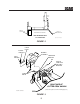
REAR OF CUTTER DECK FRONT OF CUTTER DECK DISCHARGE CHUTE OPENING VIEW FROM RIGHT SIDE OF CUTTER DECK Figure 2- GC-STC install art FIGURE 2 CATCH PLATE ELASTIC STOP NUT BLOWER ASSEMBLY MOUNTING BRACKET LOCK WASHER PIN CARRIAGE BOLTS ELASTIC STOP NUTS AND LOCK WASHERS P R O P E R Y L S E C R E V I E N G E I W T H I OL I A N D FUEL. RIGHT SIDE OF CUTTER DECK SHOWN (Note: Some parts not shown for viewing purposes.
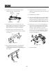
9. Install the belt to the spindle pulley. When replacing the belt, see figure below. BACK SIDE IDLER PULLEY 13. Install the hose from the blower assembly adapter to the hopper hood and secure using the 6-1/2" clamps. BLOWER PULLEY 14. Install the bag assemblies. 15. Using the weight support bar as a guide, identify the four corresponding mounting holes, and the existing hardware that will need to be removed in order to secure the weight support bar to the front of the machine as shown. See Figure 5-A.
4.1 GRASS CATCHER REMOVAL INSTRUCTIONS 6. Remove the hood assembly. 1. Prepare the work area making sure that it is a clean, safe environment. WARNING 2. Remove the bag assemblies from the grass catcher. DO NOT OPERATE WITHOUT DISCHARGE CHUTE, MULCHING KIT, OR ENTIRE GRASS CATCHER INSTALLED 3. Remove the rubber strap holding the adapter to the blower assembly. See Figure 6. 7. Re-install the side discharge chute to the opening on the cutter deck.
NOTES 6
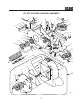
GC-STC BLOWER HOUSING ASSEMBLY 10 12 41 15 43 E 25 43 R E G N A D R E W O 46 31 14 L g B vin D mo N re A or ER R S g W O ED E nin O R LL D lea M HE TA A c TE C S L re A AT IN B befo PER S C D IS O AS R e A in T g O GR U en O N S E G D ES G L R N A U H C IS D G p to IN S T A T O 7 R 36 24 R 31 45 FO G BE E IN R IN N VE CHAL R CO A NU A LT G M'S MA W BE TINRATOR LL RAOPE TA E D S OPREA IN 34 390S0200 47 35 47 36 30 32 37 14 29 38 23 27 22 3 35 20 21 28 38 17 26 14 10 27 19 27
GC-STC BLOWER HOUSING ASSEMBLY Ref. No.
GC-STC BLOWER MOUNTING COMPONENTS 2 10 5 1 6 4 7 3 10 11 8 9 6 12 13 21 14 22 20 15 15 19 18 16 17 390S0203-A 9
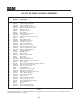
GC-STC BLOWER MOUNTING COMPONENTS Ref. No. 1 2 3 4 5 6 7 8 9 10 11 12 13 14 15 16 17 18 19 20 21 22 Part Number Description 482612 04029-04 482300 04021-08 461387 04040-14 48137-04 04001-59 481625-01 04064-15 04069-03 04067-07 481547 482248 482587 04012-04 04021-09 04030-04 04041-07 04003-11 461530 423708 04110-03 Belt Cover, GC-STC Wingnut, Plastic 3/8 Small Cap, Square Vinyl Nut, Elastic Stop 1/4-20 Adapter, Blower GC-STC, includes item #7 Flatwasher, 1/4-.312 x .750 x .
GC-STC BUCKET SUPPORT COMPONENTS (UPPER) 3 36 37 40 1 6 4 2 5 3 9 11 8 33 4 33 5 23 23 32 21 22 16 5 31 9 13 18 19 9 5 16 21 13 16 18 20 16 24 11 14 16 5 4 5 38 9 35 16 25 17 31 9 34 15 30 27 32 29 26 28 12 40 7 11 10 39
GC-STC BUCKET SUPPORT COMPONENTS (UPPER) Ref. No.
GC-STC BUCKET SUPPORT COMPONENTS (LOWER) 1 2 24 22 23 21 18 20 19 "A" 3 4 5 17 16 15 6 11 7 TO "A" 13 4 4 4 5 8 6 14 7 12 3 4 8 FRAME 5 4 9 13 10 10A STC 2002 BSC
GC-STC BUCKET SUPPORT COMPONENTS (LOWER) Ref. No. 1 2 3 4 5 6 7 8 9 10 10A 11 12 13 14 15 16 17 18 19 20 21 22 23 24 Part Number 04090-02 482321 423262 04041-07 04021-09 04020-04 04021-05 04067-07 04001-19 451514 451513 04021-02 04001-46 04001-31 482567 423312 451516 04003-02 04001-08 423198 04003-12 423197 04019-03 04040-15 04021-10 Description Pop Rivet, 3/16 x .652 Seal, Hood Tube, Upright Flatwasher, 3/8-.391 x .938 x .
GC-STC DECALS 481039 482275 481327 482293 15
LIMITED WARRANTY- COMMERCIAL ACCESSORY Any part of the Scag commercial accessory manufactured by Scag and found, in the reasonable judgment of Scag, to be defective in material or workmanship, will be repaired or replaced by an Authorized Scag Service Dealer without charge for parts and labor. The Scag accessory, including any defective part, must be returned to an Authorized Scag Service Dealer within the warranty period.
© 2003 SCAG POWER EQUIPMENT DIVISION OF METALCRAFT OF MAYVILLE, INC WWW.SCAG.COM PART NO.