THIS MANUAL CONTAINS THE OPERATING INSTRUCTIONS AND SAFETY INFORMATION FOR YOUR SCAG ACCESSORY. READING THIS MANUAL WILL PROVIDE YOU WITH MAINTENANCE AND ADJUSTMENT PROCEDURES TO KEEP YOUR ACCESSORY PERFORMING TO MAXIMUM EFFICIENCY. THE SPECIFIC MODELS THAT THIS BOOK COVERS ARE CONTAINED ON THE INSIDE COVER. BEFORE OPERATING YOUR MACHINE, PLEASE READ ALL THE INFORMATION ENCLOSED.
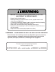
WARNING FAILURE TO FOLLOW SAFE OPERATING PRACTICES MAY RESULT IN SERIOUS INJURY. * Keep all safety shields in place. * Before performing any maintenance or service, stop the machine and remove the spark plug wire. * If a mechanism becomes clogged, stop the engine and wait for all moving parts to come to a complete halt before cleaning. * Keep hands, feet and clothing away from power-driven parts. * Read this manual completely as well as the Operator's Manual that came with your mower.
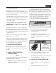
A replacement manual is available from your authorized Scag Service Dealer or by contacting: Scag Power Equipment, Service Department at P.O. Box 152, Mayville, WI 53050. You may also contact us through our website at www.scag.com. The manual for this grass catcher can be downloaded by using the model and serial number or use the contact form to make your request. Please indicate the complete model and serial number of your Scag product when requesting replacement manuals. 1.
5. To clean the hopper debris screen; 3. When dumping the hopper into a disposal area: WARNING DO NOT DUMP CLIPPINGS IN A DISPOSAL AREA THAT IS BURNING A. B. Disengage the deck drive, apply the parking brake and allow all moving parts to come to a complete stop. Pull downward on the hopper door handle to allow the hopper sweeper to remove the material from inside the hopper. See Figure 2-1. A. Disengage the deck drive and allow all moving parts to come to a complete stop. B.
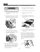
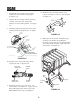
3.1 ASSEMBLY INSTRUCTIONS FOR 61" CUTTER DECK 4. Install the grass catcher pulley onto the spindle assembly. Apply loctite to both pulley setscrews and tighten. See Figure 3-1. -NOTEUse the illustrated parts list as a part number reference when following the assembly instructions. 5. Remove the "Custom-Cut" and "Turbo" baffles from the cutter deck. Using the original hardware, install the new "Custom-Cut" and "Turbo" baffles. See Figure 3-2. 1. Remove all packaging materials.
12. Install the hopper mounting brackets to the outside of the frame on the rear of the machine. See Figure 3-5. 7. Install the blower assembly to the mounting bracket and secure with the mounting pin. See Figure 3-4. Hopper Mounting Brackets 8. Align the blower assembly with the discharge opening of the cutter deck. Tighten the hardware for the mounting bracket. See Figure 3-4. Rear Frame 9. Install the quick pin through the rear hole in the discharge chute mounting bracket. See Figure 3-4.
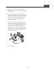
14. Install the hose from the blower assembly adapter to the hopper hood and secure using the 8-1/2" clamps. 15. Using the weight support bar (p/n 451517) as a guide, identify the four corresponding mounting holes, and the existing hardware that will need to be removed in order to secure the weight support bar to the front of the machine as shown. See Figure 3-7. 16.
4.1 GRASS CATCHER REMOVAL INSTRUCTIONS Loosen Locking Bolts 1. Prepare the machine so there is easy and safe access to the work area. Remove the key and maintain all safety related work procedures. Always wear eye and hand protection. Loosen Locking Bolts 2. Remove the rubber strap holding the adapter to the blower assembly and the large quick pin securing the blower to the discharge mounting bracket. See Figure 4-1. Remove Mounting Pins Remove Mounting Pins 2005 GC-STC removal art 2-A 3.
MAINTENANCE 5.
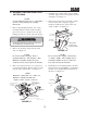
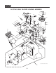
GC-STWC-CS61V BLOWER HOUSING ASSEMBLY 9 10 8 4 12 45 1 2 11 48 14 3 13 11 9 11 7 10 47 10 44 14 27 14 12 11 15 43 16 42 39 18 W E R FO E B R E E IN V HL O C UA C M A AN M LT 'S E GR B TINATO R LL RAOPE TA E D S PREA IN O 40 14 17 26 41 R A N 34 IN G 15 17 19 14 25 35 28 20 41 21 38 22 17 35 27 23 5 24 46 14 D N A R E W O L B CHUTE ENTERING CAN R S E D A L B BEFORE ENGINE E G BLOWER ROTATING BLADES STOP 24 N A D G IN T A T O R Stop en gine DISC
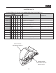
GC-STWC-CS61V BLOWER HOUSING ASSEMBLY Ref. No. Part Number Description 1 2 3 4 5 6 7 8 9 10 11 12 13 14 15 16 17 18 19 20 21 22 23 24 25 26 04067-10 481547 04066-04 04001-21 481377 482080 481428 483223 04024-02 04021-05 04041-07 43277 483209 04021-09 04030-04 424361 04003-05 04001-46 04001-81 04001-21 461928 483182 483189 04043-04 43575 482871 Pin, Ring 2-1/4" Long Lanyard, Deck Height Pin Quick Pin, 5/16" Dia.
GC-STWC-CS61V BLOWER MOUNTING COMPONENTS UNDER SIDE OF VELOCITY-PLUS CUTTER DECK SHOWN 16 16 10 10 11 5 2 26 25 4 6 23 27 23 28 7 1 24 8 3 25 26 25 6 12 13 24 9 21 14 22 20 15 15 16 18 17 19 RIGHT SIDE OF CUTTER DECK SHOWN 2006 GC-STC-V BMC 10
GC-STWC-CS61V BLOWER MOUNTING COMPONENTS Ref. No.
GC-STWC-CS61V HOPPER COMPONENTS 16 14 49 50 45 45 5 4 3 41 15 31 43 11 51 17 56 55 40 58 59 8 12 9 6 50 B 55 34 42 24 27 43 49 53 18 61 48 38 63 49 34 53 49 50 52 41 54 12 18 53 49 58 59 28 34 7 1 33 49 69 38 49 45 49 49 25 36 21 58 53 20 59 19 30 68 61 68A 35 13 46 37 57 C 26 32 44 B 49 46 A 46 49 58 59 57 72 38 22 23 65 53 64 66 33 65 29 33 38 64 21 32 49 49 49 40 49 66 65 53 63 33 19 C A 62 10 36 49 60 61 37 60 20 67
GC-STWC-CS61V HOPPER COMPONENTS Ref. No.
GC-STWC-CS61V DECALS 482871 482871 482275 MANUFACTURED UNDER ONE OR MORE OF THE FOLLOWING PATENTS: 4,487,006 4,991,382 5,133,176 6,192,666 4,885,903 4,998,948 5,826,416 6,766,633 4,920,733 5,042,239 5,832,708 6,892,519 4,967,543 5,118,617 5,865,018 PATENTS PENDING 483044 481327 481377 483037 482080 482080 14
LIMITED WARRANTY- COMMERCIAL ACCESSORY Any part of the Scag commercial accessory manufactured by Scag and found, in the reasonable judgment of Scag, to be defective in material or workmanship, will be repaired or replaced by an Authorized Scag Service Dealer without charge for parts and labor. The Scag accessory, including any defective part, must be returned to an Authorized Scag Service Dealer within the warranty period.
© 2005 SCAG POWER EQUIPMENT DIVISION OF METALCRAFT OF MAYVILLE, INC www.scag.com PART NO.