OPERATOR’S MANUAL MODEL SWZ THIS MANUAL CONTAINS THE OPERATING INSTRUCTIONS AND SAFETY INFORMATION FOR YOUR SCAG MOWER. READING THIS MANUAL CAN PROVIDE YOU WITH ASSISTANCE IN MAINTENANCE AND ADJUSTMENT PROCEDURES TO KEEP YOUR MOWER PERFORMING TO MAXIMUM EFFICIENCY. THE SPECIFIC MODELS THAT THIS BOOK COVERS ARE CONTAINED ON THE INSIDE COVER. BEFORE OPERATING YOUR MACHINE, PLEASE READ ALL THE INFORMATION ENCLOSED.
WARNING: FAILURE TO FOLLOW SAFE OPERATING PRACTICES MAY RESULT IN SERIOUS INJURY. * Keep all shields in place, especially the grass discharge chute. * Before performing any maintenance or service, stop the machine and remove the spark plug wire and ignition key. * If a mechanism becomes clogged, stop the engine before cleaning. * Keep hands, feet and clothing away from power-driven parts. * Read this manual completely as well as other manuals that came with your mower.
TABLE OF CONTENTS SUBJECT PAGE Introduction .................................................................................................. 1 General Safety Instructions .......................................................................... 1 Signal Words ............................................................................................... 1 Before Operating ......................................................................................... 2 While Operating ........................
TABLE OF CONTENTS (CONTINUED) SUBJECT PAGE Illustrated Parts List SWM-36"Cutter Deck ........................................................................ 16-17 SWM-48", 52", 61", 72" Cutter Decks...................................................... 18-19 Engine Deck................................................................................................ 20-21 Drive And Brake Components.................................................................. 22-23 Handle Assembly......................
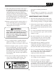
INTRODUCTION SIGNAL WORDS Your mower was built to the highest standards in the industry. However, the prolonged life and maximum efficiency of your mower depends on you following the operating, maintenance and adjustment instructions in this manual. This symbol means “Attention! Become Alert! Your Safety is Involved!" The symbol is used with the following signal words to attract your attention to safety messages found on the decals and throughout this manual.
BEFORE OPERATING WHILE OPERA TING OPERATING 1. Know the controls and how to stop quickly. 1. Start the engine when the neutral latches are in the neutral lock position, the cutter blades are disengaged, the parking brake is on and the speed adjustment lever is in the neutral position. 2. Do not allow children to operate the machine. Do not allow adults to operate the machine without proper instruction. 2. Do not run the engine in a confined area without adequate ventilation.
14. Use only Scag approved riding attachments. 9. If the cutting blades should strike a solid object or the equipment should start to vibrate abnormally, stop the engine, disconnect the spark plug wire, and check immediately for the cause. Vibration is generally a warning of trouble. Check the machine for damaged or defective parts. Repair any damage before starting the engine or operating the cutter deck. Be sure the blades are in good condition and the blade bolts are tight.
9. Always store gasoline in a safety-approved, red container. MOWER OPERATION 1. Read and understand the safety instructions before attempting to operate this machine. 10. Be careful when servicing the battery as it contains acid, which is corrosive and could cause burns to skin and clothing. 2. Before starting the engine: * Check the oil level in the engine and the hydraulic reservoir. * Fill the fuel tank with clean, fresh, leadfree gasoline. * Open the fuel valve on the bottom of the fuel tank. 11.
-NOTEWhen PTO is engaged or (possibly) disengaged, a squealing sound from the underside of the machine is normal. It is caused by the electric clutch plates meshing as the mower comes up to speed. For best equipment life, engage the clutch with the engine at 1/2 throttle, not under full load. WARNING: If you are not familiar with the operation of the hydrostatic drive and zero turn feature, practice turning and maneuvering with the hand controls before engaging the blades.
LOW CUT (1 3/4"- 3") -NOTEDue to initial belt stretch and to prevent the belt from slipping, check this adjustment after the first 2 hours, 4 hours and 8 hours of operation. MID RANGE (2 1/2"- 3 3/4") 3. Adjust the RH blade drive belt using a belt tension gauge. Adjust the belt so that the belt moves 1/2" with 10 pounds of pressure. Adjust the tension by tightening or loosening the J-bolt nut (See figure 3). HIGH CUT (3 1/4"- 4 1/2") 4. Replace the belt cover.
ANGLE BLADE BACK X DO NOT CUT IN X MUST NOT EXCEED 1/3 BLADE WIDTH 30 SC4O8G Figure 7. Blade Sharpening NEUTRAL ADJUSTMENT 1. Raise the drive wheels off the ground and block the caster wheels. 2. Remove the speed control spring and the steering control rod from the machine. (See figure 8) Steering Control Rod Bolts SC407G Spring Figure 6. Blade Spacers Bellcrank Handle SC160G Figure 8. Neutral Adjustment 3. Loosen the wing nut and let the speed adjustment bearing lever fall away from the cam.
3. Tighten the bearing securing the speed adjustment bearing lever and repeat on the opposite side. STEERING CONTROL ROD ADJUSTMENT 4. With the machine on a flat level surface, start the engine and place the speed adjustment lever into the speed that will most often be used. -NOTEThis adjustment is made to allow the steering control levers to be moved out of the neutral latch without engaging reverse. 1. Connect the steering control rods into the steering control levers on the handle.
LUBRICA TION & MAINTENANCE LUBRICATION BREAK-IN + Grease spindle until grease comes out the relief valve Compatible Greases: Lidok EP #2 (found at industrial shops) Ronex MP (Exxon service stations) 40 HOURS (WEEKLY) Shell Alvania (Shell service stations) Mobilux #2 (Mobil service stations) 100 HOURS (BIWEEKLY) Super Lub M EP #2 (Conoco service stations) 8 HOURS (DAILY) 500 HRS OR ANNUALLY COMMENTS PROCEDURE X X X X X X X X X X X X X X X X X X X X X X Check all hardware for proper tightness Change engi
TROUBLESHOOTING CUTTING CONDITIONS CAUSE CONDITION Stringers - Occasional Blades of Uncut Grass Width of Deck CURE Low engine RPM Run engine at full 3600 RPM Ground speed too fast Slow speed to adjust for conditions Wet grass Cut grass after it has dried out Dull blades, incorrect sharpening Sharpen blades Deck plugged, grass accumulation Clean underside of deck Belts slipping Adjust belt tensions Dull, worn blades Sharpen blades Incorrect blade sharpening Sharpen blades Low engine RPM
TROUBLESHOOTING CAUSE CONDITION Uneven Cut on Flat Ground - Wavy High-Low Appearance, Scalloped Cut, or Rough Contour CURE Lift worn off of blade Replace blade Blade upside down Mount with cutting edge toward ground Deck plugged, grass accumulation Clean underside of deck Too much blade angle (deck pitch) Adjust pitch and level Deck mounted improperly See your authorized SCAG dealer Bent spindle area See your authorized SCAG dealer Dull blade Sharpen blade Uneven ground May need to reduce
TROUBLESHOOTING CAUSE CONDITION Scalping - Blades Hitting Dirt or Cutting Very Close to the Ground Width of Deck CURE Low tire pressures Check and adjust pressures Ground speed too fast Slow speed to adjust for conditions Cutting too low May need to reduce ground speed, raise cutting height, change direction of cut, and/or change pitch and level Rough terrain May need to reduce ground speed, raise cutting height, and/or change direction of cut Ground speed too fast Slow speed to adjust for cond
TECHNICAL SPECIFICATIONS ENGINES General Type: Brand: Models: Horsepower: Type: Displacement: Cylinders: Governor: Exhaust Group: Fuel Pump Group: Oil Pump Group: Valve Group: Starter/Electrical: Charging System: Heavy duty industrial/commercial Kohler, Kawasaki, Kohler CV15T, CVE 20;Kaw. FC420V; Kohler 15HP& 20HP; Kaw. 14HP; Kaw.
TECHNICAL SPECIFICATIONS CUTTER DECKS Type: Construction: Cutting Width: Cutting Height Adjustment: Cutter Blades: Blade Engagement: Discharge Opening: Caster Wheels: Spindles: Spindle Pulleys: Idler Pulley: Idler Arm: Cutter Deck Belts: (CON'T) SWM 36, SWM 48, SWM 52, SWM 61, SWM 72 Out-front design with anti-scalp rollers SWM36,48: 7-gauge steel with 7-gauge (3/16") steel skirt SWM52,61,72:10-gauge steel with 7-gauge (3/16") steel skirt 35.5" (90.2 cm), 48.0 (122.0 cm), 52.0 " (132.0 cm), 61.0 " (155.
NOTES 15
32" & 36" CUTTER DECKS 41 69 9 45 47 43 11 41 69 44 44 45 68 61 59 11 46 46A 43 58 57 22 42 53 A 41 39 39A 40 42 48 7 60 58 54 14 55 50 13 56 37 18 49 52 38 36 51 A 49 2 19 37 20 21 14 55 35 40 22 21 8 20 23 24 1 1A 14 25 62 27 28 26 35 10 5 66 29 22 6 34 32 31 33 4 11 3 12 30 31 11 64 5 15 15A 16 63 67 17 SW-SWZ99CD36 16 65
36" CUTTER DECKS Ref. Part No.
48", 52", 61", & 72" CUTTER DECKS 41 73 22 59 56, 56A 61 51 44 45 40 45 44 11 43 43 11 48 45 7 51 44 58 60 47 4 39 40 11 41 46 46A 46B 41 62, 62A 63 43 64 65 49 82 61 14 76 78 42 42A 42B 52 13 40 63 9 37 74 77 67 7 38 36 36A 18 50 A 55 54 57 51 40 19 37 A 35 20 68 77 35 14 64 14 51 75 21 50 7 21 14 20 23 24 8 35 2 25 27 66 1 28 80 26 79 10 5 53 69 7 6 29 34 11 32 31 33 83 11 30 70 12 3 5 15 15A 31 16 71 81 17 SW-SWZ99CD48" 18
48, 52, 61, & 72" CUTTER DECKS Ref. Part No. No. Description 1 1 1 1 2 3 4 5 6 7 8 9 10 11 12 13 14 15 15 15 15 15A 15A 15A 16 17 18 19 20 21 22 23 24 25 26 27 28 29 NS 30 31 32 33 34 35 36 36A 37 38 39 39 39 39 39 40 41 42 42A 42B 43 Cutter Deck (Includes decals) Cutter Deck (Includes decals) Cutter Deck (Includes decals) Cutter Deck (Includes decals) Spindle Assembly Spacer, Inside Pulley Tapered Bearing (Two) Spindle Housing Grease Fitting Str.
ENGINE DECK 5 58 7 4 55 6 2 48 7 1 53 51 8 18 16 50 3 17 38 16 10 37 33 61 BLK 60 RED 9 11 45 63 34 34A 32 42 45 11A 56 65 43 15 ELECTRIC 12 START ONLY 12A 14 20 19 57 13 11 59 35 49 38 38 39 47 47A 64 35 23 27 39 41 22 21 54 62 40 45 43 28 44 26 45 43 25 29 24 46 38 43 30 31 030441698 20
ENGINE DECK Ref. Part No. No. Description 1 1 1 1 2 3 4 5 6 7 8 9 10 11 11A 12 12A 13 14 15 16 17 18 19 20 21 22 23 24 25 26 27 28 29 30 31 32 33 34 34A 35 36 37 38 39 40 Engine 14KA Kawasaki Engine 15KH Kohler Engine 17KA Kawasaki Engine 20CVE Kohler Command Retaining Ring, 1/2" Ext. "E" Hex Nut, 1/4-20 Screw, 1/4-20 x 2" Rnd. Hd. Phil. Strap, Fuel Tank Cap, Fuel Tank Pad, Rubber-Fuel Tank - Upper Fuel Tank Assy. (incl.
DRIVE AND BRAKE COMPONENTS 1 2 3, 3A 5 4 7 8 9 6 10, 10A 7 A 49 53 51 40 11 43 44 42 41 42 2 47 45 50 52 48 49 4 50 46 7 39 38 1 A 2 11 48 12 36 47 35 37 34 21 20 19 24 24A 13 14 15 18 33 25 26 32 23 17 16 22 27 30 29 28A 28B 28C SWZ99D&BC 31 22
DRIVE AND BRAKE COMPONENTS Ref. Part No. No. 1 2 3 3A 4 5 6 7 8 9 10 10A 11 12 13 14 15 16 17 18 19 20 21 22 23 24 24A 25 26 27 04050-02 04001-19 45842 45854 04062-01 04003-12 44126 04019-04 43415 48114-05 45860 45861 04001-46 481618 48004-04 422214 48679 04028-01 481502 422215 04008-01 46928 481470 04063-07 481416 48553 48587 461073 04041-28 04030-05 Description Retaining Ring, 3/4 Ext. "E" Bolt, 3/8-16 x 1" Hex Head Brake Shaft Assy. Wlmt.Small Brake Shaft Assy. Wlmt.Large Hair Pin Cotter, .094 x 1.
HANDLE ASSEMBLY 89 74 16 19 19A 11 68 81 15 90 83 16A 71 76 A 8 7 6 20 REF.
HANDLE ASSEMBLY Ref. Part No. No. Description 1 1 2 3 4 5 6 7 8 9 10 11 12 13 13A 14 15 16 16A 16A 17 18 18A 19 19A 20 20A 21 22 23 24 25 26 27 28 29 30 31 32 33 34 35 36 37 38 39 39A 40 41 42 43 44 45 46 47 48 Upper Handle Wlmt. W/Decals Upper Handle Wlmt. W/Decals Quadrant, Speed Control Hairpin, .094 x 1.
HYDRAULIC ASSEMBLY 1 2 K B 5 B E 21 13 7 4 4 3 4 29 8 D 12 J 10 19 H J 4 22 D 31 5 13 C 23 18 18A 17 28 24 32 3 20 11 10 30 A 35 10 28 11 H E 6 5 22 35 C A 13 7 4 6 15 4 14 16 10 29 8 28 11 K 19 33 12 28 10 34 11 10 9 F G 26 25 FG 10 19 10 19 21 27 030441798 26
HYDRAULIC ASSEMBLY Ref. Part No. Number Description 1 2 2 3 4 5 6 7 8 9 10 11 12 13 14 15 16 17 18 18A 19 20 21 22 23 24 25 25 26 27 28 29 30 31 32 33 34 35 Cap, Oil Reservoir Oil Reservoir (small Frame) Oil Reservior (Large Frame) Elbow, 90 deg. Female 1/4 NPT to 1/4 JIC Male Coupling, 7/16-20 SAE Flare Swivel to 1/4" Hose Push On Hose, 1/4" ID - 12" Long (Order By The Inch) Elbow, 90 deg.
HYDRAULIC PUMP ASSEMBLY 30 26 it e lS u rha K al 25 e Ov 24 23 22 27 28 1 29 19 20 21 17 16 3 15 18 11 2 14 12 13 5 6 7 8 11 10 9 4 SC165G 28
HYDRAULIC PUMP ASSEMBLY Ref. Part No. Number Description 1 2 3 4 5 6 7 8 9 10 11 12 13 14 15 16 17 18 19 20 21 22 23 24 25 26 27 28 29 30 Housing Kit (Incl. Housing, Journal Bearing) End Cap Straight Headless Pin Socket Head Screw End Cap Gasket Charge Pump Kit (Incl. Charge Cover, Gerotor Assy., O-Ring) Gerotor Assembly O-Ring Charge Relief Valve Kit Socket Head Screw Check Valve Kit (Incl. Check Plug, Spring, O-Ring, Orifice Check Valve) Bypass Valve Kit (Incl.
BLADE CLUTCH NEUTRAL INTERLOCK BLACK W/RED STRIPE GROUND ENGINE DECK WIRE HARNESS KOHLER, (SINGLE CYLINDER) & 17 HP Kawasaki PART NO. 481073 BLACK E A BLACK F B G C H D BLUE WHITE WHITE YELLOW WIRE HARNESS ADAPTER - ENGINE INSTRUMENT PANEL HARNESS SWZ99SC421G TRANSMISSION ENGINE DECK WIRE HARNESS KOHLER COMMAND V-TWIN PART NO.
HANDLE WIRE HARNESS - ELECTRIC START FUSES PART NO. 481681 YELLOW W/RED STRIPE GREEN YELLOW WHITE WHITE BLACK W/RED STRIPE MOWER ENGAGE SWITCH KEY SWITCH BRAKE SWITCH BLACK BLACK W/RED STRIPE RED GREEN A BLACK B F C G D H E WHITE RED BLACK RED BLUE TO OPERATOR PRESENCE SWITCH YELLOW TO ENGINE DECK WIRE HARNESS BLACK W/RED STRIPE RED W/ YEL STRIPE NEG HOURMETER POS HOURMETER SWZ99-481681 WIRE HARNESS WITH RELAY PART NO.
ENGINE DECK WIRE HARNESS KAWASAKI PART NO. 481074 NEUTRAL INTERLOCK BLACK W/RED STRIPE E A BLACK F B G C H D BLUE WHITE WHITE YELLOW REGULATOR RED RED ENGINE BLACK BLADE CLUTCH BLACK INSTRUMENT PANEL HARNESS SWZ99SC417G GROUND BRAKE SWITCH MOWER ENGAGE SWITCH BLACK W/RED STRIPE WHITE KEY SWITCH HANDLE WIRE HARNESS MANUAL START PART NO.
REPLACEMENT DECALS & INFORMATION HEAVY DUTY COMMERCIAL 48072 48072 48314 WARNING DANGER ROTATING BLADES AND BELTS SPINNING BLADE KEEP CLEAR CONTACT CAN INJURE 48071 48071 481040 PARKING BRAKE MANUFACTURED UNDER ONE OR MORE OF THE FOLLOWING PATENTS: CHOKE FAST 4,991,382 4,998,948 4,118,617 4,487,006 4,885,903 4,920,733 4,967,543 KEEP HANDS, FEET & CLOTHING CLEAR KEEP ALL GUARDS IN PLACE SHUT OFF ENGINE & DISENGAGE BLADE CLUTCH BEFORE SERVICING CLEAR AREA OF DEBRIS BEFORE MOWING USE CAUTION IN
REPLACEMENT DECALS & INFORMATION PARKING BRAKE CHOKE FAST OFF ON SLOW 481415 PARKING BRAKE FAST OFF ON SLOW 481423 PARKING BRAKE FAST OFF ON SLOW 481438 34
TRACKING ADJUSTMENT FAST CONTROL ROD ADJUSTMENT REVERSE SEE OPERATOR'S MANUAL NEUTRAL ADJUSTMENT OIL 481425 FORWARD 481425 SEE OPERATOR'S MANUAL SPEED CONTROL 481080 SLOW N NEUTRAL 481124 481124 48514 - 20" 48555 - 16" 35
LIMITED WARRANTY-COMMERCIAL EQUIPMENT Any part of the Scag commercial mower manufactured by Scag Power Equipment and found, in the reasonable judgment of Scag, to be defective in materials or workmanship, will be repaired or replaced by an Authorized Scag Service Dealer without charge for parts and labor. This warranty is limited to the original purchaser and is not transferable. Proof of purchase will be required by the dealer to substantiate any warranty claims.
© 1999 SCAG POWER EQUIPMENT DIVISION OF METALCRAFT OF MAYVILLE, INC. PART NO.