OPERATOR’S MANUAL SFW Walk-Behind Model: SFW36-16BV SFW48-16BV Congratulations on owning a Scag mower! This manual contains the operating instructions and safety information for your Scag mower. Reading this manual can provide you with assistance in maintenance and adjustment procedures to keep your mower performing to maximum efficiency. The specific models that this book covers are listed on the inside cover. Before operating your machine, please read all the information enclosed.
WARNING FAILURE TO FOLLOW SAFE OPERATING PRACTICES MAY RESULT IN SERIOUS INJURY OR DEATH. • Read this manual completely as well as other manuals that came with your mower. • ALWAYS FOLLOW OSHA APPROVED OPERATION. • DO NOT operate on steep slopes. • Always travel across slopes. • DO NOT mow on wet grass. Wet grass reduces traction and steering control. • Keep all shields in place, especially the grass discharge chute.
Table of Contents R Table of Contents SECTION 1 - GENERAL INFORMATION. ..................................................................................1 1.1 Introduction............................................................................................................................................1 1.2 Direction Reference............................................................................................................................1 1.
Table of Contents R SECTION 6 - ADJUSTMENTS..................................................................................................19 6.1 DRIVE CONTROL ADJUSTMENTS...........................................................................................................19 6.2 Throttle Control and Choke Adjustments.............................................................................19 6.3 BELT ADJUSTMENT......................................................................................
Section 1 R GENERAL INFORMATION 1.1 Introduction USE ONLY SCAG APPROVED ATTACHMENTS AND ACCESSORIES. Your mower was built to the highest standards in the industry. However, the prolonged life and maximum efficiency of your mower depends on you following the operating, maintenance and adjustment instructions in this manual. Attachments and accessories manufactured by companies other than Scag Power Equipment are not approved for use on this machine. See Section 8-1.
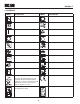
Section 1 R 1.4 Symbols SYMBOL DESCRIPTION SYMBOL DESCRIPTION Choke Transmission Parking Brake Spinning Blade 48071S On/Start Spring Tension on Idler Off/Stop Oil Falling Hazard Thrown Object Hazard Fast Slow Continuously Variable - Linear Cutting Element - Basic Symbol Pinch Point Cutting Element - Engage Hour meter/Elapsed Operating Hours Cutting Element - Disengage STT Models CE Mark 481039S Seat must be installed under the seat hold down bracket during installation.
Section 2 R SAFETY INFORMATION 2.1 Introduction Danger Your mower is only as safe as the operator. Carelessness or operator error may result in serious bodily injury or death. Hazard control and accident prevention are dependent upon the awareness, concern, prudence, and proper training of the personnel involved in the operation, transport, maintenance and storage of the equipment. Make sure every operator is properly trained and thoroughly familiar with all of the controls before operating the mower.
Section 2 R 13. Keep flammable objects (cigarettes, matches, etc.), open flames and sparks away from the fuel tank and fuel container. Use only approved containers. 7. If the operator(s) or mechanic(s) cannot read English or Spanish, it is the owner's responsibility to explain this material to them. Contact your local Authorized Scag Dealer for a Spanish Decal Kit. 14. Equipment must comply with the latest requirements per SAE J137 and/or ANSI/ASAE S279 when driven on public roads. 8.
Section 2 R WARNING DANGER DO NOT use your hand to dislodge the clogged discharge chute. Use a stick or other device to remove clogged material after the engine has stopped running and the blades have stopped turning. DO NOT run the engine inside a building or a confined area without proper ventilation. Exhaust fumes are hazardous and contain carbon monoxide which can cause brain injury and death. 7. Be alert for holes, rocks, roots and other hidden hazards in the terrain. Keep away from any dropoffs.
Section 2 R 4. Keep all nuts, bolts and screws tight, to ensure the machine is in safe working condition. Check blade mounting bolts frequently to be sure they are tight. 5. Do not change the engine governor settings or overspeed the engine. See the engine operator's manual for information on engine settings. 6. To reduce fire hazard, keep the cutting units, drives, muffler and engine free of grass, leaves, excessive grease, oil and dirt. 7. Park the machine on level ground. 8.
Section 2 R 2.
Section 3 R SPECIFICATIONS 3.1 ENGINE General Type.................................................................................................Heavy Duty Industrial/Commercial Gasoline Brand........................................................................................................................................................ Briggs & Statton Horsepower: (Scag Model SFW36-16BV)......................................................................................... 16 HP (Spec.
Section 3 R Spindle Pulleys...................................................................................................................................................Split Steel Cutter Deck Belts....................................................................B-section with Kevlar Cord. Self-Adjusting, Self-Tightening Electric Clutch Type.................................................................................................Ogura Heavy Duty PTO Clutch Brake 3.
Section 4 R OPERATING INSTRUCTIONS 2. Mower Deck Switch (Figure 4-1). Used to engage and disengage the mower drive system. Pulling up on the switch will engage the deck drive. Pushing down on the switch will disengage the deck drive. CAUTION Do not attempt to operate this mower unless you have read this manual. Learn the location and purpose of all controls and instruments before you operate this mower. 3. Engine Choke Control (Figure 4-1). Used to start a cold engine. 4.
Section 4 R 5. Left Steering / Brake Control (Figure 4-1). Used to control the mower's left wheel when traveling forward or reverse. Pull upward to apply brake. 4.3 INITIAL RUN-IN PROCEDURES First Day of Use or Approximately 20 Hours 6. Right Steering / Brake Control (Figure 4-1). Used to control the mower's right wheel when traveling forward or reverse. Pull upward to apply brake. 1. Check all belts for proper alignment and wear at 2, 4 and 8 hours. 7. Deck Lift (Figure 4-1).
Section 4 R Reverse Travel 4.5 GROUND TRAVEL AND STEERING - IMPORTANT - Caution If you are not familiar with the operation of a walk behind mower with a transmission, the steering and ground speed operations should be learned and practiced in an open area, away from buildings, fences, or obstructions. Disengage power to the mower before backing up. Do not mow in reverse unless absolutely necessary and then only after observation of the entire area behind the mower.
Section 4 R 4.6 ENGAGING THE DECK DRIVE (CUTTER BLADES) 4.7 HILLSIDE OPERATION 1. Set the throttle at about 3/4 speed. Do not attempt to engage the deck drive at high speed as this shortens the electric clutch life — use only moderate engine speed when engaging the deck drive. WARNING DO NOT operate on steep slopes. ALWAYS FOLLOW OSHA APPROVED OPERATION. 2. Engage the deck drive by pulling out on the yellow switch, located on the instrument panel, to the engage position. See Figure 4-2. 1.
Section 4 R 4.9 AFTER OPERATION 4.11 MOVING MOWER WITH ENGINE STOPPED 1. Wash the entire mower after each use. Do not use high pressure spray or direct the spray onto electrical components. To “free-wheel” or move the mower around without the engine running, engage the neutral latches, shift the transmission to neutral and move the mower by hand. - IMPORTANT Do not wash a hot or running engine. Cold water will damage the engine. Use compressed air to clean the engine if it is hot. 4.
Section 4 R 4.13 ADJUSTING CUTTING HEIGHT CUTTING HEIGHT 1-1/2 The mower deck can be adjusted from a height of 1-1/2 inches to 4-1/2 inches at 1/4-inch intervals. To adjust the cutting height: 1-3/4 2 2-1/4 2-1/2 2-3/4 WARNING 3 3-1/4 3-1/2 3-3/4 DO NOT adjust the cutting height with the mower blades rotating. Disengage the power to the cutter blades and then adjust cutting height. 4 4-1/4 4-1/2 LH - 483894 1. Disengage the power to the cutter blades. Figure 4-4. Cutting Height Decal 2.
Section 5 R TROUBLESHOOTING CUTTING CONDITIONS Condition Cause Stringers - Occasional Low engine RPM Blades of Uncut Grass Width of Deck Cure Run engine at full RPM Ground speed too fast Slow speed to adjust for conditions Wet grass Cut grass after it has dried out Dull blades, incorrect sharpening Sharpen blades Deck plugged, grass accumulation Clean underside of deck Belts slipping Adjust belt tension SGB020 Streaking - Strips of Dull, worn blades Uncut Grass in Cutting Path Incorrect bl
Section 5 R TROUBLESHOOTING CUTTING CONDITIONS (CONT'D) Condition Cause U ne v en C ut on F lat Lift worn from blade Ground - Wavy High-Low Appearance, Scalloped Blade upside down Cut, or Rough Contour Cure Replace blade Mount with cutting edge toward ground Deck plugged, grass accumulation Clean underside of deck Too much blade angle (deck pitch) Adjust pitch and level Deck mounted improperly See your authorized SCAG dealer Bent spindle area See your authorized SCAG dealer Dull blade Sharpen
Section 5 R TROUBLESHOOTING CUTTING CONDITIONS (CONT'D) Condition Cause Scalping - Blades Hitting Low tire pressures Dirt or Cutting Very Close to the Ground Ground speed too fast Width of Deck Cure Check and adjust pressures Slow speed to adjust for conditions Cutting too low May need to reduce ground speed, raise cutting height, change direction of cut, and/or change pitch and level Rough terrain May need to reduce ground speed, raise cutting height, and/or change direction of cut Ground speed
Section 6 R ADJUSTMENTS 6.1 DRIVE CONTROL ADJUSTMENTS 6.3 BELT ADJUSTMENT 1. Adjust the steering control rods so that there is approximately 3/4" clearance from the bottom of the rod to the bottom of the neutral latch slot when in the drive position. See Figure 6-1. WARNING Before removing any guards, shut the engine off and remove the ignition key. 2. Adjust the steering brake rods so that the brakes do not apply until the steering levers are pulled tight to the handles.
Section 6 R Check the distance from the top of the cutter deck to the floor at the rear RH side of the cutter deck directly behind the cutter deck height adjustment bracket. Next check the distance from the top of the cutter deck to the floor at the front RH side of the cutter deck directly in front of the cutter deck height adjustment bracket. The measurement at the front of the cutter deck should be the same as the rear of the deck. Make these measurements at the LH side of the cutter deck also.
Section 6 R INSERT 0.015 FEELER GAUGE HERE If the air gap is too narrow, the clutch armature may drag when disengaged, resulting in premature failure. If the air gap is too wide, the clutch may be slow to engage as the magnet must pull the armature in from a greater distance. Figure 6-4. Clutch Air Gap Adjustment 3. Tighten or loosen the adjusting bolt as needed to acheive the 0.015 inch airgap. See Figure 6-5. Perform this operation at all three inspection windows.
Section 7 R MAINTENANCE 7.1 MAINTENANCE CHART - RECOMMENDED SERVICE INTERVALS HOURS Break-In (First 10) Procedure 8 20 40 100 200 Comments 500 X Check all hardware for tightness X C h e c k a l l b e l t s f o r p r o p e r See paragraph 7.6 alignment X Check engine oil level See paragraph 7.3 X *Clean mower X *Clean air filter element See paragraph 7.5 X Check condition of blades See paragraph 7.7 X Sharpen cutter blades See paragraph 7.7 X Check tire pressure See paragraph 7.
Section 7 R MAINTENANCE CHART - RECOMMENDED SERVICE INTERVALS (CONT'D) HOURS Break-In (First 10) Procedure 8 40 100 200 Comments 500 X Check hardware for tightness X Change engine oil filter See paragraph 7.3 X Replace engine fuel filter See paragraph 7.3 X Adjust electric PTO clutch See paragraph 6.6 7.2 Lubrication GREASE FITTING LUBRICATION CHART LOCATION LUBRICATION INTERVAL LUBRICANT NO.
Section 7 R 7.3 Engine Oil 7.4 Engine Fuel System ENGINE OIL FILLER DANGER To avoid injury from burns, allow the mower to cool before removing the fuel tank cap and refueling. A. Filling the Fuel Tank ENGINE OIL FILTER Fill the fuel tank at the beginning of each operating day to within one (1) inch below the filler neck. Do not overfill. Use clean, fresh unleaded gasoline with a minimum octane rating of 87 and a maximum of 10% Ethanol. Figure 7-1.
Section 7 R 9. If fuel is spilled on clothing, change clothing immediately and wash affected skin. 2. Remove the air cleaner and inspect. 3. Clean or replace the air cleaner and foam pre-cleaner as recommended by the engine manufacturer. 10. Replace gas cap and tighten securely. B. Replacing In-Line Fuel Filter Elements 4. Replace the air cleaner cover and be sure to snap the two latches closed.
Section 7 R sharpened. Remove the blades for sharpening. See "Blade Replacement." 2. Raise the mower deck to the highest position. Place the lanyard pin in the highest cutting height position to prevent the cutter deck from falling. - NOTE - 3. Secure the cutter blades to prevent them from rotating, (use the optional Blade Buddy tool P/N 9212, to assist in securing the cutter blades), remove the blade attaching bolt. Remove the cutter blade, bolt, lockwasher and flatwasher from the spindle shaft.
Section 8 R ILLUSTRATED PARTS LIST 8.1 SCAG APPROVED ATTACHMENTS AND ACCESSORIES. Attachments and accessories manufactured by companies other than Scag Power Equipment are not approved for use on this machine.
Section 8 R 36" CUTTER DECK 2 4 3 6 2 5 7 3 9 8 10 41 8 4 40 11 12 38 39 42 14 13 12 38 15 5 16 4 17 25 1 18 26 19 21 32 19 20 33 22 34 23 24 35 27 33 28 36 29 30 31 28 37
Section 8 R 36" CUTTER DECK Ref. No. Part No.
Section 8 R 48" CUTTER DECK 2 4 3 6 5 4 2 5 3 7 7 17 2 5 8 3 9 47 46 10 44 4 45 13 48 8 8 14 11 15 17 12 14 44 18 16 19 20 19 4 20 21 22 5 23 19 24 25 19 26 20 28 1 27 29 43 20 37 38 28 29 39 30 31 40 32 38 33 41 34 35 42 36 30
Section 8 R 48" CUTTER DECK Ref. No. Part No.
Section 8 R CUTTER DECK CONTROLS 1 30 2 31 7 29 6 28 5 A 4 5 3 8 12 28 10 12 8 32 8 11 8 14 12 13 9 17 9 27 18 A 14 12 26 9 25 24 20 19 21 23 22 21 32 15 16 9 17 15 16
Section 8 R CUTTER DECK CONTROLS Ref. No. 1 2 3 4 5 6 7 8 9 10 11 12 13 14 15 16 17 18 19 20 21 22 23 24 25 26 27 28 29 30 31 32 Part No.
Section 8 R HANDLE ASSEMBLY 56 1 58 57 2 59 64 8 3 4 5 55 60 60 6 64 53 62 54 63 20 47 48 9 10 7 52 51 11 8 46 66 49 44 27 65 12 42 50 13 46 45 43 14 41 18 40 15 17 39 16 18 19 38 21 15 16 36 37 20 25 22 20 28 35 23 20 15 29 34 30 24 27 20 26 20 21 31 33 20 34 32 SFW 2009 HA
Section 8 R HANDLE ASSEMBLY Ref. No. 1 2 3 4 5 6 7 8 9 10 11 12 13 14 15 16 17 18 19 20 21 22 23 24 25 26 27 28 29 30 31 32 Part No.
Section 8 R ENGINE DECK 1 4 5 47 46 45 6 2 52 7 9 8 49 50 51 3 10 54 53 44 43 48 40 42 34 35 38 36 39 29 41 37 A 11 41 15 12 14 13 16 17 33 18 32 20 19 B 21 25 22 30 A 23 30 26 27 28 B 31 29 24 SFW2009ED 36
Section 8 R ENGINE DECK Ref. No. 1 2 3 4 5 6 7 8 9 10 11 12 13 14 15 16 17 18 19 20 21 22 23 24 25 26 27 28 29 30 31 32 33 34 35 36 37 38 39 40 41 42 43 44 45 46 47 48 49 50 51 52 53 54 Part No.
Section 8 R ELECTRICAL SYSTEM AND THROTTLE CONTROL 1 P S O W E C R E Q A G U IP 6 M 3 7 5 8 9 8 13 10 11 14 12 38 E N T 2 4 4
Section 8 R ELECTRICAL SYSTEM AND THROTTLE CONTROL Ref. No. 1 2 3 4 5 6 7 8 9 10 11 12 Part No.
Section 8 R REPLACEMENT DECALS AND INFORMATION PLATES WARNING WARNING INSTALL BELT COvER BEFORE OPERATING MACHINE READ OPERATOR'S MANUAL DO NOT OPERATE WITHOUT DISCHARGE CHUTE, MULCHING kIT, OR ENTIRE GRASS CATCHER INSTALLED 483402 483405 1 2 WARNING SPINNING BLADES ROTATING BLADES AND BELTS kEEP CLEAR * keep hands, feet & clothing clear * keep all guards in place * Shut off engine & disengage blade clutch before servicing * Use caution in directing discharge * Read instruction manual before o
Section 8 R REPLACEMENT DECALS AND INFORMATION PLATES Ref. No. 1 2 3 4 5 6 7 8 9 10 11 12 13 14 15 16 Part No.
Section 8 R SFW ELECTRICAL SCHEMATIC Operator Presence Switch BLACK KEY SWITCH WHITE BLACK BLACK HOURMETER YELLOW Operator Presence Switch BLK W/RED STRIPE BLK W/RED STRIPE MOWER ENGAGE WHITE YELLOW BLUE WHITE TO ENGINE DECK WIRE HARNESS TO HANDLE BAR WIRE HARNESS BLACK BLUE CLUTCH BLUE ENGINE CHARGE ENGINE MAG KILL YELLOW WHITE WHITE WHITE BLK W/RED STRIPE GROUND 42 NEUTRAL SWITCH
LIMITED WARRANTY - SFW Any part of the Scag commercial mower manufactured by Scag Power Equipment and found, in the reasonable judgment of Scag, to be defective in materials or workmanship, will be repaired or replaced by an Authorized Scag Service Dealer without charge for parts and labor during the periods specified below. This warranty is limited to the original purchaser and is not transferable. Proof of purchase will be required by the dealer to substantiate any warranty claims.
© 2008 Scag Power Equipment Division of Metalcraft of Mayville, Inc.