OPERATOR’S MANUAL Tiger Cub Models: STC48V-26BS STC52V-23BV STC52V-25CV STC52V-25CV-FR STC61V-23BV STC61V-25CV STC61V-25CV-FR Congratulations on owning a Scag mower! This manual contains the operating instructions and safety information for your Scag mower. Reading this manual can provide you with assistance in maintenance and adjustment procedures to keep your mower performing to maximum efficiency. The specific models that this book covers are listed on the inside cover.
WARNING FAILURE TO FOLLOW SAFE OPERATING PRACTICES MAY RESULT IN SERIOUS INJURY OR DEATH. • Read this manual completely as well as other manuals that came with your mower. • DO NOT operate on steep slopes. To check a slope, attempt to back up it (with the cutter deck down). If the machine can back up the slope without the wheels slipping, reduce speed and use extreme caution. • Under no circumstances should the machine be operated on slopes greater than 15 degrees.
Table of Contents R TABLE OF CONTENTS SECTION 1 - GENERAL INFORMATION. ..................................................................................1 1.1 Introduction............................................................................................................................................1 1.2 Direction Reference............................................................................................................................1 1.
Table of Contents R SECTION 6 - ADJUSTMENTS..................................................................................................22 6.1 PARKING BRAKE ADJUSTMENT.............................................................................................................22 6.2 TRAVEL ADJUSTMENTS...........................................................................................................................22 6.3 Throttle Control and Choke Adjustments....................................
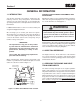
Section 1 R GENERAL INFORMATION 1.1 Introduction USE ONLY SCAG APPROVED ATTACHMENTS AND ACCESSORIES. Your mower was built to the highest standards in the industry. However, the prolonged life and maximum efficiency of your mower depends on you following the operating, maintenance and adjustment instructions in this manual. Attachments and accessories manufactured by companies other than Scag Power Equipment are not approved for use on this machine. See Paragraph 8.1.
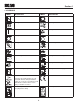
Section 1 R 1.4 Symbols SYMBOL DESCRIPTION SYMBOL DESCRIPTION Choke Transmission Parking Brake Spinning Blade 48071S On/Start Spring Tension on Idler Off/Stop Oil Falling Hazard Thrown Object Hazard Fast Slow Continuously Variable - Linear Cutting Element - Basic Symbol Pinch Point Cutting Element - Engage Hour meter/Elapsed Operating Hours Cutting Element - Disengage STT Models CE Mark 481039S Seat must be installed under the seat hold down bracket during installation.
Section 2 R SAFETY INFORMATION 2.1 Introduction Danger Your mower is only as safe as the operator. Carelessness or operator error may result in serious bodily injury or death. Hazard control and accident prevention are dependent upon the awareness, concern, prudence, and proper training of the personnel involved in the operation, transport, maintenance and storage of the equipment. Make sure every operator is properly trained and thoroughly familiar with all of the controls before operating the mower.
Section 2 R 7. If the operator(s) or mechanic(s) cannot read English or Spanish, it is the owner's responsibility to explain this material to them. 12. DO NOT add fuel to a running or hot engine. Allow the engine to cool for several minutes before adding fuel. Never fuel indoors or inside enclosed trailers. 8. DO NOT wear loose fitting clothing. Loose clothing, jewelry or long hair could get tangled in moving parts.
Section 2 R 3. To prevent tipping or loss of control, start and stop smoothly, avoid unnecessary turns and travel at reduced speed. 15. The machine and attachments should be stopped and inspected for damage after striking a foreign object, and damage should be repaired before restarting and operating the machine. 4. When using any attachment, never direct the discharge of material toward bystanders or allow anyone near the machine while in operation. Caution 5.
Section 2 R Any or all parts of the Roll-Over Protection System MUST NOT be removed. Failure to adhere to this guideline could result in injury or death. 2.5 Roll-over protection system WARNING FOLDABLE Roll-over protection system (if equipped) Reduce speed when turning, operating on slopes, slick or wet surfaces. Allow extra distance to stop. WARNING Stay off of slopes too steep for safe operation. To check a slope, attempt to back up it (with the cutter deck down).
Section 2 R 2. Remove the hairpin cotter pins and remove the two (2) lock pins. See Figure 2-2. WARNING 3. Lower the roll bar to the down position. Failure to properly inspect and maintain the seat belt can cause serious injury or loss of life. 4. To raise the roll bar, lift the bar to the upright position. 5. Install the two (2) lock pins through the hole, secure with the two (2) hairpin cotter pins and tighten the tension knobs. See Figure 2-2. Remove the seat belt from the retainer brackets. 1.
Section 2 R 2.6 Maintenance Considerations & storage WARNING 1. Never make adjustments to the machine with the engine running unless specifically instructed to do so. If the engine is running, keep hands, feet, and clothing away from moving parts. Hydraulic fluid is under high pressure. Keep body and hands away from pinholes or nozzles that eject hydraulic fluid under high pressure. If you need service on your hydraulic system, please see your authorized Scag dealer.
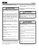
Section 2 R 2.7 SAFETY AND INSTRUCTIONAL DECALS WARNING INSTALL BELT COvER BEFORE OPERATING MACHINE READ OPERATOR'S MANUAL 483402 483407 FORWARD F R REvERSE 481568 ! Avoid injury from burns. Shut off engine before removing fuel tank cap. 483406 CAUTION ! 483397 Avoid injury from burns. Shut off engine before removing fuel tank cap.
Section 3 R SPECIFICATIONS 3.1 ENGINE General Type.................................................................................................Heavy Duty Industrial/Commercial Gasoline Brand............................................................................................................................................Briggs & Statton, Kohler Horsepower: (Scag Model STC52V-23BV, STC61V-23BV).............................................................. 23 HP (Spec.
Section 3 R Travel Speed: Forward.........................................................................................................................................................0-10 MPH Reverse...........................................................................................................................................................0-5 MPH -NOTE- The machine will travel at 10 mph for transport purposes.
Section 4 R OPERATING INSTRUCTIONS 2. Mower Deck Switch (Figure 4-1). Used to engage and disengage the mower drive system. Pulling up on the switch will engage the deck drive. Pushing down on the switch will disengage the deck drive. CAUTION Do not attempt to operate this mower unless you have read this manual. Learn the location and purpose of all controls and instruments before you operate this mower. 3. Engine Choke Control (Figure 4-1). Used to start a cold engine. 4.
Section 4 R 6. Fuse Holders (Figure 4-1). Two 20-amp fuses protect the mower’s electrical system. To replace fuses, pull fuse out of the socket and install a new fuse. 14. Deck Release Lever (Figure 4-1). Used to lock the cutter deck in the transport position. Push the foot pedal forward and pull back on the release lever to release the cutter deck for normal mowing. 7. Left Steering Control (Figure 4-1). Used to control the mower's left wheel when traveling forward or reverse. 15.
Section 4 R Learn to feather the steering controls to obtain a smooth operating action. 4.4 STARTING THE ENGINE Practice operating the mower until you are comfortable with the controls before proceeding to mow. CAUTION DO NOT USE STARTING FLUIDS. Use of starting fluids in the air intake system may be potentially explosive or cause a “runaway” engine condition that could result in engine damage and/or personal injury.
Section 4 R Reverse Travel 4.6 ENGAGING THE DECK DRIVE (CUTTER BLADES) 1. Set the throttle at about 3/4 speed. Do not attempt to engage the deck drive at high speed as this shortens the electric clutch life — use only moderate engine speed when engaging the deck drive. Caution Disengage power to the mower before backing up. Do not mow in reverse unless absolutely necessary and then only after observation of the entire area behind the mower. 2.
Section 4 R 4.7 HILLSIDE OPERATION 4.9 AFTER OPERATION 1. Wash the entire mower after each use. Do not use high pressure spray or direct the spray onto electrical components. WARNING - IMPORTANT - DO NOT operate on steep slopes. To check a slope, attempt to back up it (with the cutter deck down). If the machine can back up the slope without the wheels slipping, reduce speed and use extreme caution. Under no circumstances should the machine be operated on slopes greater than 15 degrees.
Section 4 R 4. Keep mower and discharge chute clean. 4.11 MOVING MOWER WITH ENGINE STOPPED 5. When mowing wet or tall grass, mow the grass twice. Raise the mower to the highest setting for the first pass and then make a second pass to the desired height. To “free-wheel” or move the mower around without the engine running, rotate the dump valve levers counterclockwise. See Figure 4-4. Disengage the parking brake and move the mower by hand.
Section 4 R 3. Insert the lanyard pin into the cutting height index at the desired cutting height. Push forward on the deck lift foot lever, hold in place and pull back on the deck release lever. See Figure 4-6. Slowly release the foot pedal. A deck height decal is located on the cutting height index as an aid in adjusting the deck to the desired height. See Figure 4-5. ROTATE LEvER TENSION kNOB Figure 4-7. Adjusting Steering Levers 4. The control handle can also be adjusted in two different positions.
Section 5 R TROUBLESHOOTING CUTTING CONDITIONS Condition Cause Stringers - Occasional Low engine RPM Blades of Uncut Grass Width of Deck Cure Run engine at full RPM Ground speed too fast Slow speed to adjust for conditions Wet grass Cut grass after it has dried out Dull blades, incorrect sharpening Sharpen blades Deck plugged, grass accumulation Clean underside of deck Belts slipping Adjust belt tension SGB020 Streaking - Strips of Dull, worn blades Uncut Grass in Cutting Path Incorrect bl
Section 5 R TROUBLESHOOTING CUTTING CONDITIONS (CONT'D) Condition Cause U ne v en C ut on F lat Lift worn from blade Ground - Wavy High-Low Appearance, Scalloped Blade upside down Cut, or Rough Contour Cure Replace blade Mount with cutting edge toward ground Deck plugged, grass accumulation Clean underside of deck Too much blade angle (deck pitch) Adjust pitch and level Deck mounted improperly See your authorized SCAG dealer Bent spindle area See your authorized SCAG dealer Dull blade Sharpen
Section 5 R TROUBLESHOOTING CUTTING CONDITIONS (CONT'D) Condition Cause Scalping - Blades Hitting Low tire pressures Dirt or Cutting Very Close to the Ground Ground speed too fast Width of Deck Cure Check and adjust pressures Slow speed to adjust for conditions Cutting too low May need to reduce ground speed, raise cutting height, change direction of cut, and/or change pitch and level Rough terrain May need to reduce ground speed, raise cutting height, and/or change direction of cut Ground speed
Section 6 R ADJUSTMENTS 6.1 PARKING BRAKE ADJUSTMENT STC2002BA WARNING Do not operate the mower if the parking brake is not operable. Possible severe injury could result. LOOSEN HERE The parking brake linkage should be adjusted whenever the parking brake lever is placed in the “ENGAGE” position and the parking brake will allow the mower to move. If the following procedures do not allow you to engage the parking brake properly, contact your Scag dealer for further brake adjustments.
Section 6 R Neutral Adjustment Tracking Adjustment 1. Be sure the dump valve levers are in the run position and the steering control levers are in the neutral lock position. Caution 2. With an operator in the seat, start the engine and disengage the parking brake. Stop the engine and remove the key from the ignition before making any adjustments. Wait for all moving parts to come to a complete stop before beginning work. 3.
Section 6 R A. Stop the machine and place the steering control levers in the neutral position. Loosen the lock nuts securing the ball joints at each end of the RH steering control rod. Rotate the control rod to lengthen the rod and tighten the lock nuts. This will cause the control rod to stroke the RH pump less, slowing down the RH wheel. See Figure 6-3. 6.6 CUTTER DECK ADJUSTMENTS Cutter deck level, pitch and height are set at the factory.
Section 6 R Cutter Deck Pitch Cutter Deck Height The pitch of the cutter deck should be equal between the front and rear of the cutter deck for proper cutting performance. To check for proper deck pitch, be sure that the mower is on a flat, level surface and the tires are properly inflated. The cutter deck height adjustment is made to ensure that the cutter deck is cutting at the height indicated on the cutting height index gauge.
Section 6 R 3. Check the cutter deck cutting height by placing the lanyard pin in the 3" position on the cutting height index. Release the deck from the transport position and allow the deck to move to the 3" cutting height position. To adjust the Custom-Cut Baffle height: 1. Place the cutter deck in the transport position. 2. Remove the hardware securing the Custom-Cut Baffle to the cutter deck. See Figure 6-8. 4. Check the measurement from the floor to the cutter blade tip.
Section 6 R 1 2 3 1 2 3 A A Custom-Cut Baffle Adjustment Mounting Slot Mounting Hardware Location Slot “A” Height (inches) Hole 1 3” Hole 2 3-1/2” Hole 3 4” Figure 6-8. 3-Position Custom-Cut Baffle Adjustment 1 2 3 4 A B 1 2 34 A B Custom-Cut Baffle Adjustment Mounting Slot Selected Slot “A” Height (inches) Hole 1 3-3/4” Slot “B” Height (inches) Mounting Hardware Location Hole 2 Hole 3 Hole 4 4-1/4” 4-3/4” 5-1/4” Hole 2 3-1/2” Hole 3 4” Figure 6-9.
Section 7 R MAINTENANCE 7.1 MAINTENANCE CHART - RECOMMENDED SERVICE INTERVALS HOURS Break-In (First 10) Procedure 8 20 40 100 200 Comments 500 X Check all hardware for tightness X Check hydraulic oil level X C h e c k a l l b e l t s f o r p r o p e r See paragraph 7.8 alignment See paragraph 7.3 Check hydraulic hoses for leaks Use extreme caution when checking the hydraulic hoses. See paragraph 2.6 X Check engine oil level See paragraph 7.4 X *Clean mower See paragraph 7.
Section 7 R MAINTENANCE CHART - RECOMMENDED SERVICE INTERVALS (CONT'D) HOURS Procedure Break-In (First 10) 8 40 100 200 Comments 500 X Apply grease to fittings See paragraph 7.2 X Check hardware for tightness X Change engine oil filter See paragraph 7.4 X Check hydraulic oil level See paragraph 7.3 X Replace engine fuel filter See paragraph 7.5 X Drain hydraulic system and Use SAE 20W50 Motor Oil. replace hydraulic oil See paragraph 7.
Section 7 R GREASE FITTING LUBRICATION Lubricant Interval Lithium MP White Grease 2125 (40 Hours/Weekly) Chassis Grease (100 Hours/Bi-monthly) Chassis Grease (200 Hours/Monthly) 6 Chassis Grease (500 Hours/Yearly) 4 1 3 5 7 2 6 8 1 2 4 5 3 Figure 7-1.
Section 7 R - IMPORTANT - 7.3 Hydraulic System The hydraulic oil should be changed if you notice the presence of water or a rancid odor to the hydraulic oil. A. Checking Hydraulic Oil Level The hydraulic oil level should be checked after the first 10 hours of operation. Thereafter, check the oil after every 200 hours of machine operation or monthly, whichever occurs first. 1. Park the mower on a level surface and stop the engine. 2. Place a suitable container under the hydraulic oil filter.
Section 7 R C. Changing Hydraulic Oil Filter Element A. Checking Engine Crankcase Oil Level The engine oil level should be checked after every 8 hours of operation or daily as instructed in the Engine Operator’s Manual furnished with this mower. The hydraulic oil filter should be changed after every 500 hours of operation or annually, whichever occurs first. 1. Remove the oil filter element and properly discard it. See Figure 7-3. Fill the new filter with clean oil and install the filter.
Section 7 R 2. Use only an approved gasoline container. FUEL FILTER 3. Never remove the gas cap or add fuel with the engine running. Allow the engine to completely cool before fueling. 4. Never fuel the machine indoors or in an enclosed trailer. 5. Never store the machine or fuel container where there is an open flame, spark or pilot light such as on a water heater or other appliances. 6. Never fill containers inside a vehicle or on a truck or trailer bed with a plastic liner.
Section 7 R A. Charging the Battery 7.7 Battery Refer to the battery charger’s manual for specific instructions. WARNING Under normal conditions the engine’s alternator will have no problem keeping a charge on the battery. If the battery has been completely discharged for a long period of time, the alternator may not be able to recharge the battery, and a battery charger will be required. Lead-acid batteries produce flammable and explosive gases.
Section 7 R B. Blade Sharpening 7.8 DRIVE BELTS All drive belts are spring-loaded and self-tensioning, however after the first 2, 4, 8 and 10 hours of operation, the belts should be checked for proper alignment and wear. Thereafter, check the belts after every 40 hours of operation or weekly, whichever occurs first. - NOTE If possible, use a file to sharpen the blade. Using a wheel grinder may burn the blade. - NOTE - - NOTE - DO NOT sharpen the blades beyond 1/3 of the width of the blade.
Section 7 R - NOTE - 7.10 TIRES The front of the machine will have to be raised slightly to remove the blade bolt from the cutter spindle. Check the tire pressures after every 8 hours of operation or daily. Caster Wheels Drive Wheels 4. To install the new cutter blade, put the flat washer onto the blade bolt and slide the bolt into the hole in the cutter blade. 25 PSI 12 PSI 7.
Section 8 R ILLUSTRATED PARTS LIST 8.1 SCAG APPROVED ATTACHMENTS AND ACCESSORIES. Attachments and accessories manufactured by companies other than Scag Power Equipment are not approved for use on this machine.
Section 8 R 48V & 52V CUTTER DECKS 14 55 55 52, 52A 14 29 80 53 53 65 55 18 64 60 62 61 56 14 72 48 53 4 73 29 21 49 67 13 74 3 49 11 31 51 49 84 54 81 83 13 15 50 66 28 49 83 13 23 20 87 83 17 3 3 32 3 12 2 * 70 26 30 59 58 66 63 56 29 21 3 82 3 75 76 33 77 6 7 8 70 26 84 35 36 24 10 78 79 88 86 37 5 25 13 66 89 1 27 38 85 57 40 19 41 22 68 42 69 34 46 47 29 37 9 43 16 44 45 71 STC 2006 CD4852 Rev.
Section 8 R 48V & 52V CUTTER DECKS Ref. No. 1 2 3 4 5 6 7 8 9 10 11 12 13 14 15 16 17 18 19 20 21 22 23 24 25 26 27 28 29 30 31 32 33 34 35 36 37 38 39 40 41 42 43 44 45 46 47 48 49 50 Part No.
Section 8 R 61V CUTTER DECK 24 14 53 52 72 32 18 51 29 21 56 4 65 93 49 11 67 64 60 62 61 54 50 79 31 "A" 56 55 59 58 66 63 53 94 13 91 13 32 29 79 15 56 66 21 30 23 78 13 92 20 56 17 82 "A" 81 2 80 12 80 3 81 28 87 88 2 80 80 80 6 7 8 76 77 78 88 80 75 13 33 26 35 80 71 36 89 10 90 13 84 83 37 5 25 85 74 66 27 73 12 38 86 1 40 19 57 41 22, 22A 68 42 69 34 46 70 29 47 37 9 43 16 44 45 STWC 2006 CD61 40
Section 8 R 61V CUTTER DECK Ref. No. 1 2 3 4 5 6 7 8 9 10 11 12 13 14 15 16 17 18 19 20 21 22 23 24 25 26 27 28 29 30 31 32 33 34 35 36 37 38 39 40 41 42 43 44 45 46 47 48 49 50 Part No.
Section 8 R CUTTER DECK CONTROLS 18 46 20 5 4 3 38 12 21 2 26 33 27 17 1 6 13 7 41 42 45 14 46 15 37 36 16 11 9 30 8 10 22 32 24 40 43 34 44 24 28 35 25 19 29 24 23 24 25 19 29 23 24 25 28 31 CUTTER DECK 42 STC 2006 CDC
Section 8 R CUTTER DECK CONTROLS Ref. No. 1 2 3 4 5 6 7 8 9 10 11 12 13 14 15 16 17 18 19 20 21 22 23 24 25 26 27 28 29 30 31 32 33 34 35 36 37 38 39 40 41 42 43 44 45 46 Part No.
Section 8 R SHEET METAL COMPONENTS 57 3 58 22 23 59 41 60 24 A 5 2 29 25 6 67 15 43 A 53 18 19 47 11 7 8 20 54 10 9 Seat Assy.
Section 8 R SHEET METAL COMPONENTS Ref. No. 1 2 3 4 5 6 7 8 9 10 11 12 13 14 15 16 17 18 19 20 21 22 23 24 25 26 27 28 29 30 31 32 33 34 35 36 37 38 39 40 Part No.
Section 8 R STC FIXED ROLL-OVER PROTECTION SYSTEM 4 6 7 6 6 6 6 4 6 1 Seat Assy.
Section 8 R STC FIXED ROLL-OVER PROTECTION SYSTEM Ref. No. 1 2 3 4 5 6 7 8 Part No. 9506 04001-145 04021-19 483412 04040-13 461990 483451 483412 461990 Description STC Fixed ROPS Accessory (incl. all items listed) Bolt, Hex Head 1/2-13 x 3-1/2” Nut, Center Lock 1/2-13 Retractable Seat Belt Flatwasher, 1/2-.562 x 1.375 x .
Section 8 R STC FOLDABLE ROLL-OVER PROTECTION SYSTEM 4 12 13 12 1 12 12 12 4 12 1 9 10 11 Seat Assy.
Section 8 R STC FOLDABLE ROLL-OVER PROTECTION SYSTEM Ref. No. 1 2 3 4 5 6 7 8 9 10 11 12 13 14 Part No. 9512 04001-145 04021-19 483412 04040-13 481625-03 04062-06 483262 04021-19 424407 04001-145 461990 483451 483412 461990 Description STC Foldable ROPS Accessory (incl. all items listed) Bolt, Hex Head 1/2-13 x 3-1/2” Nut, Center Lock 1/2-13 Retractable Seat Belt Flatwasher, 1/2-.562 x 1.375 x .
Section 8 R DRIVE SYSTEM COMPONENTS 5 23 22 24 29 17 2 10 26 25 21 20 1 18 2 15 6 3 28 30 28 14 31 27 1 1 4 19 32 7 11 8 9 7 11 12 16 10 13 10 1 12 16 STC 2005 DSC 50
Section 8 R DRIVE SYSTEM COMPONENTS Ref. No. Part No.
Section 8 R ENGINE & ATTACHING PARTS 5 14 1 17 7 2 4 11 3 4 12 8 15 16 6 9 13 4 10 4 2008 STC EAPBS 52
Section 8 ENGINE AND ATTACHING PARTS Ref. Part No. No. 1 2 3 4 5 6 7 8 9 10 11 12 13 14 15 16 17 483439 483401 483685 423770 424107 41031 04019-04 482510 04003-23 04104-01 483288 483416 483266 424133 423555 04001-11 04001-19 04011-12 483280-01 04003-31 04019-03 424415 Description Engine, Briggs & Stratton 26hp ELS Engine, Briggs & Stratton 23hp Vanguard Engine, Kohler Command 25hp Bumper, Rear Shield, Rear (48” & 52”) Weight, Rear Shield ( 61” Only) Nut, Serr. Flange 3/8-16 Extension, Oil Drain 3.
Section 8 R STEERING COMPONENTS 1 2 3 4 5 18 39 18 41 38 40 6 7 8 30 25 20 32 19 17 37 27 26 15 34 17 21 42 28 4 5 35 34 24 33, 33A 35 31 9 29, 29A 23 22 To Pump 14 16 13 12 11 10 STC 2002 SSC 54
Section 8 R STEERING COMPONENTS Ref. No. 1 2 3 4 5 6 7 8 9 10 11 12 13 14 15 16 17 18 19 20 21 22 23 24 25 26 27 28 29 30 31 32 33 34 35 36 37 38 39 40 41 42 43 Part No.
Section 8 R BRAKE COMPONENTS 4 5 18 7 6 8 9 44 36 10 38 26 25 34 33 30 24 21 6 20 22 23 20 19 27 35 24 32 20 40 16 17 35 43 41 24 2 26 28 42 1 31 11 3 15 14 13 12 STC 2002 BSC 56
Section 8 R BRAKE COMPONENTS Ref. No. 1 2 3 4 5 6 7 8 9 10 11 12 13 14 15 16 17 18 19 20 21 22 23 24 25 26 27 28 29 30 31 32 33 34 35 36 37 38 39 40 41 42 43 44 Part No.
Section 8 R FUEL AND HYDRAULIC SYSTEM 9 11 A 55 G 2 C 8 B D G 27 12 9 11 14 15 1 12 7 36 F 10 7 36 1 4 A 13 12 17 1 4 B 23 24 39 k E 16 3 55 21 22 30 28 50 9 56 29 5 20 19 F 6 31 44 53 59 C D 9 25 18 19 J 20 45 46 3 20 19 18 k 19 59 4 18 19 M J 20 19 36 18 37 18 33 47 48 E 44 31 42 TO ENGINE 34 M 58 37 26 4 36 46 41 L 38 26 35 32 54 43 L 26 57 51 40 48 47 49 STC 2007 FHS 58
Section 8 R FUEL AND HYDRAULIC SYSTEM Ref. No. 1 2 3 4 5 6 7 8 9 10 11 12 13 14 15 16 17 18 19 20 21 22 23 24 25 26 27 28 29 30 31 32 33 34 35 Part No.
Section 8 R ELECTRICAL SYSTEM 1 27 29 23 38 25 30 39 40 6 20 41 26 31 32 14 34 12 33 21 10 17 11 16 15 18 10 19 11 24 7 35 8 36 12 37 11 12 9 10 11 5 4 2 3 13 STC 2005 ESKA 60
Section 8 R ELECTRICAL SYSTEM Ref. No. 1 2 3 4 5 6 7 8 9 10 11 12 13 14 15 16 17 18 19 20 21 22 23 24 25 26 27 28 29 30 31 32 33 34 35 36 37 38 39 40 41 42 43 44 45 Part No.
Section 8 R BDP-10A HYDRAULIC PUMP ASSEMBLY 29 l ea Kit 20 S ul 21 a rh ve 23 22 1718 O 15 14 13 16 30 12 11 19 25 PORT "A" SIDE 3 1 24 27 26 5 4 6 7 2 24 28 8 10 PORT "B" SIDE 9 62 30
Section 8 R BDP-10A HYDRAULIC PUMP ASSEMBLY Ref. No. Part No.
Section 8 R REPLACEMENT DECALS AND INFORMATION PLATES 1 2 8 MANUFACTURED UNDER ONE OR MORE OF THE FOLLOWING PATENTS: 4,487,006 4,885,903 4,920,733 4,967,543 4,991,382 4,998,948 5,042,239 5,117,617 5,133,176 5,826,416 5,832,708 5,865,018 6,192,666 6,766,633 6,892,519 6,996,962 7,065,946 7,197,863 48404 PATENTS PENDING 5 11 FORWARD F R REvERSE 482100 6 Heavy-Duty Commercial 481971 13 7 WARNING INSTALL BELT COvER BEFORE OPERATING MACHINE READ OPERATOR'S MANUAL 4 483402 9 10 12 18 STC 200
Section 8 R REPLACEMENT DECALS AND INFORMATION PLATES Ref. No. 1 2 3 4 5 6 7 8 9 10 11 12 13 14 15 16 17 18 ** Part No.
Section 8 R ELECTRICAL SCHEMATIC PTO SWITCH DIODE BRIGGS & STRATTON ADAPTER HARNESS MAIN HARNESS RELAY GRN W/BLK STRIPE GREEN GRN W/WHT STRIPE YELLOW RED W/YEL STRIPE RED RED WHITE RED GREEN BLACK RED W/YEL STRIPE RED BLUE RED LIGHT BLUE RED W/YEL STRIPE ENGINE YELLOW KEY SWITCH WHITE RED GRN W/WHT STRIPE BLACK ENGINE GROUND SOLENOID SOLENOID 20 AMP FUSES SOLENOID "B+" KOHLER ADAPTER HARNESS GRN W/WHT STRIPE WHITE BRAKE INTERLOCK SWITCH ENGINE PLUG YELLOW WHITE YELLOW RE
LIMITED WARRANTY - COMMERCIAL EQUIPMENT Any part of the Scag commercial mower manufactured by Scag Power Equipment and found, in the reasonable judgment of Scag, to be defective in materials or workmanship, will be repaired or replaced by an Authorized Scag Service Dealer without charge for parts and labor during the periods specified below. This warranty is limited to the original purchaser and is not transferable. Proof of purchase will be required by the dealer to substantiate any warranty claims.
GARANTÍA LIMITADA - EQUIPO COMERCIAL Toda pieza del cortacésped comercial Scag fabricada por Scag Power Equipment que, según criterio razonable de Scag, presente materiales o mano de obra defectuosos será reparada o reemplazada por un distribuidor autorizado Scag sin cargo por las piezas ni mano de obra durante los períodos especificados abajo. Esta garantía se limita al comprador original y no es transferible. Para acceder a cualquier reclamo de garantía, el distribuidor requerirá el comprobante de compra.
Sección 7 -NOTAAsegúrese que la cuchilla se instale con la aleta de izamiento hacia la parte superior de la plataforma de corte. 5. Instale el espaciador en el perno de la cuchilla e introduzca el perno en el eje de corte. 6. Instale la tuerca hexagonal en el perno de la cuchilla en la parte superior del eje de corte. Evite el giro de las cuchillas con un apriete de 75 lbs-pie. (Vea la Figura 79). 7.10 LLANTAS Verifique las presiones de las llantas después de cada 8 horas de operación o diariamente.
B. Afilado de las cuchillas -NOTASi es posible, use una lima para afilar la cuchilla. Si usa una esmeriladora, puede quemar la cuchilla. -NOTANO afile las cuchillas más de 1/3 del ancho de la cuchilla. 1. Afile el borde de corte en el mismo bisel que el original (Vea la Figura 7-8). Sólo afile la parte superior del borde de corte para mantener el filo. Sección 7 3.
Sección 7 ADVERTENCIA: LAS BATERÍAS PRODUCEN GASES EXPLOSIVOS. Cargue la batería en un espacio bien ventilado de modo que se puede disipar los gases producidos durante la carga. Las tasas de carga entre 3 y 50 amperios son satisfactorias si no provocan excesivos gases, si no arrojan demasiado electrolito o si la batería no está muy caliente (encima de 125° F).
7.6 FILTRO DE AIRE DEL MOTOR A. Limpieza y/o reemplazo del elemento del filtro de aire Para cualquier filtro de aire, el ambiente de operación determina los períodos de servicio del filtro de aire. Inspeccione y limpie el filtro de aire después de cada 100 horas de operación o cada dos semanas, lo que ocurra primero y reemplace el elemento si es necesario. -NOTAEn condiciones de mucho polvo, puede ser necesario verificar el elemento una o dos veces al día para prevenir daños al motor. 1.
Sección 7 7.5 SISTEMA DE COMBUSTIBLE DEL MOTOR PELIGRO: Para evitar quemaduras, permita que el cortacésped se enfríe antes de quitar la tapa del tanque de combustible y rellenar. A. Llenado del tanque de combustible Llene el tanque de combustible al inicio de cada día de operación hasta 1 pulgada debajo del cuello del rellenador. No llene demasiado. Use gasolina limpia, libre de plomo con un octanaje mínimo de 87 y un máximo de 10% de Etanol. NO use combustible E85.
4. Llene el depósito a 3-1/4" de la parte superior del rellenador con aceite para motor SAE 20W50. Sección 7 RELLENADOR DE ACEITE DEL MOTOR 5. Reemplace la tapa de relleno del depósito. Arranque el motor y conduzca hacia adelante y hacia atrás durante dos minutos. Verifique el nivel de aceite en el depósito. Si es necesario, agregue aceite al depósito. C.
Sección 7 7.3 SISTEMA HIDRÁULICO A. Verificación del nivel de aceite hidráulico El nivel del aceite hidráulico se debe verificar después de las primeras 10 horas de operación. Después, verifique el aceite después de cada 200 horas de operación de la máquina o mensualmente, lo que ocurra primero. -IMPORTANTESi el nivel de aceite se encuentra bajo de manera constante, revise si existen pérdidas y corríjalas inmediatamente. 1.
3 6 Sección 7 CONEXIONES DE GRASA DE LUBRICACIÓN Intervalo de lubricación Grasa blanca de litio MP 2125 (40 horas/semanalmente) Grasa de chasis (100 horas/cada dos meses) Grasa de chasis (200 horas/mensualmente) Grasa de chasis (500 horas/anualmente) 4 5 7 1 2 6 8 1 2 4 5 3 Figure 7.1.
Sección 7 TABLA DE MANTENIMIENTO - INTERVALOS DE SERVICIO RECOMENDADOS (CONTINUACIÓN) USO INICIAL 8 (Primeros 10) HORAS 40 100 200 500 Procedimiento Verifique el nivel del aceite hidráulico X Cambie el filtro de aceite del motor X Verifique que la tornillería esté bien ajustada X Aplique grasa a las conexiones X Observaciones Vea el párrafo 7.2 Vea el párrafo 7.4 Vea el párrafo 7.3 Ajuste el embrague eléctrico PTO X Vea el párrafo 7.
Sección 7 MANTENIMIENTO 7.1 TABLA DE MANTENIMIENTO - INTERVALOS DE SERVICIO RECOMENDADOS USO INICIAL 8 HORAS 20 40 100 200 500 Procedimiento Observaciones (Primeros 10) Revise la presión de las llantas X Aplique grasa a las conexiones X Verifique el estado de las cuchillas X *Limpie el cortacésped X Verifique el nivel de aceite del motor X Vea el párrafo 2.
Sección 6 1 2 3 1 3 2 A A Ajuste del deflector de corte personalizado Ranura de montaje Ranura "A" Altura (pulgadas) Ubicación de accesorios de montaje Orificio1 3” Orificio 2 3-1/2” Orificio 3 4” Figura 6-9.
-NOTASi se tuvo que realizar un ajuste, asegúrese que la plataforma de corte se pueda bloquear fácilmente en la posición de transporte. Ajuste del deflector de corte personalizado El deflector de corte personalizado está diseñado para entregar un óptimo flujo de aire y un desempeño de corte superior en cualquier tipo de césped. El deflector personalizado puede levantarse o bajarse para personalizar en forma precisa el desempeño de la plataforma para el tipo de césped que se está cortando.
Sección 6 4 X 1/ 2 1/ 2 3 1/ 4 4 5 CU HE TTI IG NG HT AFLOJE AQUÍ 1/ 1 2 AJUSTE DE LA VARILLA TUERCA DE BLOQUEO VARILLA DE CONTROL STC2006CDP SP Figura 6-5. Ajuste de la plataforma de corte -NOTAPara evitar la oscilación de la plataforma de corte, las cuatro cadenas suspendidas de la plataforma de corte deben estar tensionadas. Si las cuatro cadenas no están bajo tensión y la plataforma oscila, debe reajustar la plataforma de corte como se explicó en los procedimientos mencionados anteriormente.
6.6 AJUSTES DE LA PLATAFORMA DE CORTE El nivel de la plataforma de corte, la inclinación y la altura se ajustan en fábrica. Sin embargo, si deben realizarse estos ajustes alguna vez, los siguientes procedimientos lo ayudarán a obtener el ajuste apropiado de la plataforma de corte. -NOTAAntes de proceder con los ajustes de la plataforma de corte, asegúrese de que todas las llantas estén infladas apropiadamente.
Sección 6 Ajuste de alineación PRECAUCIÓN: Detenga el motor y quite la llave del encendido antes de realizar cualquier ajuste. Espere que todas las partes móviles se detengan antes de comenzar a trabajar. PRECAUCIÓN: El motor y la unidad motriz pueden calentarse durante la operación, causando heridas por quemaduras. Permita que el motor y los componentes de transmisión se enfríen antes de realizar cualquier ajuste.
6.2 AJUSTES DE DESPLAZAMIENTO Se tendrán que realizar ajustes neutrales o de alineación si: A. Las palancas de control de dirección están en la posición neutral y la máquina se arrastra hacia adelante o hacia atrás. (Vea Ajuste neutral). B. Las palancas del control de dirección están en la posición completamente hacia adelante y el cortacésped se tira a un lado o al otro al desplazarse hacia adelante. (Ajuste de alineación, Vea página 27). Ajuste neutral 1.
Sección 6 6. Reemplace las ruedas motrices y pruebe el freno. 6.1 AJUSTE DEL FRENO DE ESTACIONAMIENTO 5. Repita los pasos 2-4 en el lado derecho de la máquina. AJUSTES ADVERTENCIA: NO opere el cortacésped si el freno de estacionamiento no está en correcto estado de funcionamiento. Podrían causarse lesiones graves.
Sección 5 SOLUCIÓN DE FALLAS (CONTINUACIÓN) CONDICIÓN Raspadoras - Las cuchillas pegan en la tierra o están cortando muy cerca al terreno CAUSA Baja presión de las llantas Velocidad demasiado alta Corte demasiado bajo Terreno rugoso Velocidad demasiado alta Ancho de la plataforma de corte SGB 022 Corte lateral - Cresta en el centro de la trayectoria de corte Césped mojado SOLUCIÓN Verifique y ajuste las presiones Disminuya la velocidad para ajustarse a las condiciones del terreno Se puede tener que re
Sección 5 SOLUCIÓN DE FALLAS (CONTINUACIÓN) Limpie la parte de abajo de la plataforma Ajuste la inclinación y el nivel Césped acumulado debajo de la plataforma de corte Demasiado ángulo en la cuchilla (inclinación de la plataforma de corte) Plataforma de corte montada incorrectamente Monte la cuchilla con el filo hacia el terreno Cuchilla montada invertida Reemplace la cuchilla Levantador de la cuchilla desgastado Corte disparejo en terreno disparejo Apariencia baja y alta ondulada, corte volado o pe
Sección 5 IDENTIFICACIÓN DE FALLAS EN LAS CONDICIONES DE CORTE CONDICIÓN Largueros - Corte irregular de césped Ancho de la plataforma de corte CAUSA Bajas revoluciones (rpm) del motor SOLUCIÓN Opere el motor a su máxima RPM Ajuste la tensión de la correa Correas patinando Limpie la parte de abajo de la plataforma Césped acumulado debajo de la plataforma de corte Afile las cuchillas Cuchillas desafiladas, afilado incorrecto Corte el césped una vez que se seque Césped mojado Disminuya la velocida
Sección 4 PEDAL DE AJUSTE DE ALTURA 1 1/4 X 2 1/2 3 1/2 4 1/4 5 CU HE T T IG ING HT PIN DE AMARRE STC 2006 ACH SP Figura 4-5 Ajuste de altura de corte 4.14 REMOLQUE (accesorio de enganche opcional) 1. Nunca permita niños ni otras personas en el equipo remolcado. 2. Remolque sólo con una máquina que tenga un accesorio de enganche diseñado para remolcar. Sólo conecte el equipo remolcado en el punto de enganche. 3.
4.12 RECOMENDACIONES PARA CORTAR EL CÉSPED 1. No corte con cuchillas desafiladas. Una cuchilla desafilada desgarrará el césped, dando como resultado una mala apariencia del césped y requiriendo potencia adicional del motor. 2. La tolva de descarga no debe quitarse y debe mantenerse en su posición más baja para desviar hacia abajo el césped cortado y cualquier objeto que se encuentre sobre el mismo. Dirija la descarga lateral lejos de aceras o de calles para minimizar la limpieza de los recortes de césped.
Sección 4 4. Puede producirse una pérdida de tracción al desplazarse bajando una cuesta. El peso se transfiere a la parte delantera de la máquina y puede causar que las ruedas motrices se deslicen, causando pérdida de frenado o dirección. PELIGRO: Para evitar quemaduras, permita que el cortacésped se enfríe antes de quitar la tapa del tanque de combustible y rellenar. 5. Mantenga las llantas correctamente infladas. 4.8 ESTACIONAMIENTO DEL CORTACÉSPED 1.
Para dirigirse a la derecha mientras se desplaza en reversa, permita que la palanca derecha de dirección se mueva hacia adelante. Cuanto más se permita al control desplazarse hacia adelante, más rápido girará el cortacésped a la derecha. Para detener el desplazamiento en reversa, permita que las palancas de dirección vuelvan a la posición neutral. Si el cortacésped debe ser estacionado, coloque las asas en la posición neutral de bloqueo y accione el freno de estacionamiento. 4.
Sección 4 4.5 DESPLAZAMIENTO EN EL TERRENO Y DIRECCIÓN -IMPORTANTESi no está familiarizado con la operación de una máquina con dirección de palanca y/o transmisiones hidrostáticas, debe practicar las operaciones de conducción y velocidad en el terreno en un área abierta, lejos de edificios, cercas, u obstrucciones. Practique hasta que se sienta cómodo con el manejo de la máquina antes de tratar de cortar. Aprenda la operación en terreno plano antes de operar en pendientes.
4.2 SISTEMA DE BLOQUEO DE SEGURIDAD El cortacésped está equipado con un sistema de bloqueo de seguridad que evita que el motor arranque a menos que la transmisión de plataforma esté desconectada, que el freno de estacionamiento esté accionado, las palancas de control de dirección en la posición neutral y el perador esté en el asiento.
Sección 4 5. Horómetro (Figura 4-1). Indica el número de horas que ha operado el motor. Opera cuando el interruptor de la llave de encendido está en la posición ON. Ha fijado los recordatorios para el mantenimiento del motor y los cambios de aceite del sistema hidráulico. El mantenimiento programado empezará a destellar 2 horas antes de la hora establecida y continuará destellando hasta 2 horas después. Reinicia automáticamente. 6. Portafusibles (Figura 4-1).
Sección 4 INSTRUCCIONES DE OPERACIÓN PRECAUCIÓN: No trate de operar este cortacésped a menos que haya leído este manual. Aprenda la ubicación y el propósito de todos los controles e instrumentos antes de operar este cortacésped. 4.1 IDENTIFICACIÓN DE CONTROLES E INSTRUMENTOS Antes de operar el cortacésped, debe familiarizarse con todos los controles del cortacésped y el motor. Es importante conocer la ubicación, función y operación de estos controles para la operación segura y eficiente del cortacésped.
Sección 3 3.3 TRACTOR (CONTINUACIÓN) -NOTA- La máquina se desplazará a 10 Mph (16 Velocidad de desplazamiento: Adelante ................................................................................ 0-10 MPH (0-16 Kph) Kph) para fines de transporte. Para un mejor desempeño de corte, la velocidad de Reversa .................................................................................. 0-5 MPH (0-8 Kph) desplazamiento hacia adelante debe ajustarse en función de las condiciones de corte. 3.
3.1 MOTOR Sección 3 ESPECIFICACIONES Tipo general ............................................................................... Industrial de servicio pesado/Comercial de gasolina Marca ......................................................................................... Briggs & Statton, Kohler Potencia ..................................................................................... 23 HP (Espec.#) (Scag Modelo STC52V-23BV, STC61V-23BV) ........................................................
2.
Sección 2 9. Tenga cuidado al revisar las cuchillas. Forre las cuchillas o use guantes y tenga cuidado al dar servicio a las cuchillas. Sólo reemplace o afile las cuchillas. NUNCA enderece ni suelde las cuchillas. 10. Mantenga todas las partes en buenas condiciones de funcionamiento. Reemplace todas las calcomanías desgastadas o dañadas. 11. Use soportes de gato para apoyar componentes cuando sea necesario. 12. Libere cuidadosamente la presión de los componentes que tengan energía almacenada.
Sección 2 1. Nunca realice ajustes a la máquina con el motor en operación a menos que se le indique específicamente hacerlo así. Si el motor está funcionando, mantenga las manos, los pies, y la ropa lejos de las piezas móviles. Se recomienda examinar diariamente el cinturón de seguridad para detectar señales de daño.
ADVERTENCIA: El cinturón de seguridad debe estar sujetado firmemente durante la operación. No hacerlo así podría ocasionar lesiones graves o la muerte. SISTEMA PLEGABLE DE PROTECCIÓN CONTRA VUELCO (SI VIENE EQUIPADO) Sección 2 Baje la barra contra vuelco sólo cuando sea absolutamente necesario. 1. Para bajar la barra contra vuelco, afloje la perilla de tensión en las barras del lado izquierdo y derecho. Vea la Figura 2-1. 2.
Sección 2 14. Desconecte la potencia a los accesorios cuando los transporte o cuando no esté usándolos. 15. La máquina y los accesorios deben detenerse e inspeccionarse para ver si han sufrido daños después de golpear un objeto extraño; el daño debe repararse antes de reiniciar y operar la máquina. PRECAUCIÓN: NO toque el motor ni el silenciador mientras el motor está funcionando, ni inmediatamente después de detenerlo. Estas zonas pueden estar lo suficientemente calientes como para causar una quemadura.
15. No opere sin la tolva de descarga lateral instalada y en la posición baja o con un recogedor de césped o placa desmenuzadora opcionales completamente instalados. 16. Verifique a intervalos frecuentes que los pernos de montaje de la cuchilla estén correctamente ajustados. 17. Asegúrese de que todas las conexiones hidráulicas estén apretadas y que todas las mangueras hidráulicas y las líneas estén en buen estado antes de arrancar la máquina. 2.4 CONSIDERACIONES DE OPERACIÓN 1.
Sección 2 3. NO permita que los niños se suban o jueguen en la máquina, no es un juguete. 4. Retire del área que debe ser cortada todos los objetos que pudieran ser recogidos y arrojados por las cuchillas. 5. NO lleve pasajeros. 6. NO opere el equipo bajo la influencia de alcohol o drogas. 7. Si el operador o mecánico no puede leer inglés o español, es responsabilidad del propietario explicarles este material. 8. NO use ropa muy holgada.
2.1 INTRODUCCIÓN Sección 2 INFORMACIÓN DE SEGURIDAD Palabra de señalización: Su cortacésped es tan seguro como el operador. El error o descuido del operador puede ocasionar lesiones personales graves o la muerte. El control de riesgos y la prevención de accidentes dependen del conocimiento, el interés, la prudencia, y el entrenamiento apropiado del personal relacionado con la operación, el transporte, mantenimiento y almacenamiento del equipo.
SÍMBOLO DESCRIPCIÓN SÍMBOLO DESCRIPCIÓN Lento Rápido Elemento cortante – Conectar Punto de contacto Elemento cortante - símbolo básico Continuamente variable – Lineal 481039S Horómetro/Horas de operación transcurridas Elemento cortante – Desconectar Peligro de objetos lanzados Lea el manual del operador Mantenga alejados a los curiosos 3
1.3 SERVICIO AL MOTOR Y A LOS COMPONENTES DEL TREN DE TRANSMISIÓN Los detalles sobre servicio y reparación del motor, las bombas hidráulicas y cajas de cambios, no están cubiertos en este manual; sólo se proporcionan instrucciones de mantenimiento de rutina y de servicio Símbolos ISO SÍMBOLO DESCRIPCIÓN general.
Sección 1 INFORMACIÓN GENERAL 1.1 INTRODUCCIÓN SÓLO USE DISPOSITIVOS APROBADOS POR SCAG. Su cortacésped se fabricó según las normas más exigentes de la industria. Sin embargo, la duración de la vida útil y el logro de la máxima eficiencia de su cortacésped dependen de que se sigan las instrucciones de operación, mantenimiento y ajuste indicadas en este manual. Si requiere información o servicio adicionales, contacte con su distribuidor de Scag Power Equipment.
TABLA DE CONTENIDO (CONTINUACIÓN) TEMA PÁGINA Sección 6 - Ajustes 6.1 Ajuste del freno de estacionamiento ..................................................................................... 25 6.2 Ajustes de desplazamiento .................................................................................................... 26 6.3 Ajustes de los controles de aceleración y estrangulación ..................................................... 27 6.4 Ajuste de la correa ......................................
TABLA DE CONTENIDO TEMA PÁGINA Sección 1 - Información general 1.1 Introducción ............................................................................................................................1 1.2 Referencia de instrucciones ....................................................................................................1 1.3 Servicio al motor y a los componentes del tren de transmisión ..............................................2 1.3 Símbolos ..........................................
ADVERTENCIA: EL INCUMPLIMIENTO DE LAS PRÁCTICAS SEGURAS DE OPERACIÓN PUEDE RESULTAR EN LESIONES GRAVES. * Mantenga todas las guardas en su posición, especialmente la de la tolva de descarga de césped. * Antes de realizar cualquier mantenimiento o servicio, detenga la máquina y quite el cable de la bujía y la llave de encendido. * Si un mecanismo se atasca, detenga el motor antes de limpiar. * Mantenga las manos, los pies y la ropa lejos de las partes móviles.
MANUAL DEL OPERADOR STC48V-26BS STC52V-23BV STC52V-25CV STC52V-25CV-FR STC61V-23BV STC61V-25CV STC61V-25CV-FR ESTE MANUAL CONTIENE LAS INSTRUCCIONES DE OPERACIÓN Y LA INFORMACIÓN DE SEGURIDAD PARA SU CORTACÉSPED SCAG. LA LECTURA DE ESTE MANUAL LE PUEDE AYUDAR EN EL MANTENIMIENTO Y LOS PROCEDIMIENTOS DE AJUSTE A FIN DE MANTENER SU CORTACÉSPED TRABAJANDO A LA MÁXIMA EFICIENCIA. LOS MODELOS ESPECÍFICOS CUBIERTOS POR ESTE MANUAL ESTÁN INDICADOS EN LA CUBIERTA INTERIOR.