OPERATOR’S MANUAL Turf Tiger Propane Model: STT52V-25CH-LP STT61V-25CH-LP Congratulations on owning a Scag mower! This manual contains the operating instructions and safety information for your Scag mower. Reading this manual can provide you with assistance in maintenance and adjustment procedures to keep your mower performing to maximum efficiency. The specific models that this book covers are listed on the inside cover. Before operating your machine, please read all the information enclosed.
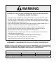
WARNING FAILURE TO FOLLOW SAFE OPERATING PRACTICES MAY RESULT IN SERIOUS INJURY OR DEATH. • Read this manual completely as well as other manuals that came with your mower. • DO NOT operate on steep slopes. To check a slope, attempt to back up it (with the cutter deck down). If the machine can back up the slope without the wheels slipping, reduce speed and use extreme caution. • Under no circumstances should the machine be operated on slopes greater than 15 degrees.
Table of Contents R Table of Contents SECTION 1 - GENERAL INFORMATION. ..................................................................................1 1.1 Introduction............................................................................................................................................1 1.2 Direction Reference............................................................................................................................1 1.
Table of Contents R SECTION 5 - TROUBLESHOOTING CUTTING CONDITIONS................................................20 SECTION 6 - ADJUSTMENTS..................................................................................................23 6.1 PARKING BRAKE ADJUSTMENT.............................................................................................................23 6.2 TRAVEL ADJUSTMENTS...........................................................................................................
Section 1 R GENERAL INFORMATION 1.1 Introduction USE ONLY SCAG APPROVED ATTACHMENTS AND ACCESSORIES. Your mower was built to the highest standards in the industry. However, the prolonged life and maximum efficiency of your mower depends on you following the operating, maintenance and adjustment instructions in this manual. Attachments and accessories manufactured by companies other than Scag Power Equipment are not approved for use on this machine. See Section 8-1.
Section 1 R 1.
Section 2 R SAFETY INFORMATION 2.1 Introduction Danger Your mower is only as safe as the operator. Carelessness or operator error may result in serious bodily injury or death. Hazard control and accident prevention are dependent upon the awareness, concern, prudence, and proper training of the personnel involved in the operation, transport, maintenance and storage of the equipment. Make sure every operator is properly trained and thoroughly familiar with all of the controls before operating the mower.
Section 2 R 3. DO NOT allow children to ride or play on the machine, it is not a toy. 10. Be sure the interlock switches are functioning correctly. 4. Clear the area to be mowed of objects that could be picked up and thrown by the cutter blades. 11. Fuel is flammable; handle it with care. Fill the LP tank outdoors. Never fill it indoors. Clean up any spillage before starting the engine. 5. DO NOT carry passengers. 12. Keep flammable objects (cigarettes, matches, etc.
Section 2 R 3. Stay two cut widths away from slopes, drop offs, ditches and retaining walls. 15. Disengage power to the attachments when transporting or when not in use. 4. To prevent tipping or loss of control, start and stop smoothly, avoid unnecessary turns and travel at reduced speed. 16. The machine and attachments should be stopped and inspected for damage after striking a foreign object, and damage should be repaired before restarting and operating the machine. 5.
Section 2 R 2.5 Roll-Over Protection System Lower the roll bar only when absolutely necessary. 1. To lower the roll bar, loosen the tension knob on both the left hand and right hand bar. See Figure 2-1. WARNING 2. Remove the hairpin cotter pins and remove the two (2) lock pins. See Figure 2-2. Keep the roll bar in the raised and locked position and the seat belt securely fastened during operation. Failure to do so could cause serious injury or loss of life. 3. Lower the roll bar to the down position.
Section 2 R The potential exposure of the seat belt to severe environmental conditions make it crucial to inspect the seat belt system regularly. It is recommended that the seat belt be inspected on a daily basis for signs of damage.
Section 2 R 2.6 Maintenance Considerations & Storage WARNING 1. Never make adjustments to the machine with the engine running unless specifically instructed to do so. If the engine is running, keep hands, feet, and clothing away from moving parts. Hydraulic fluid is under high pressure and can penetrate skin causing injury. If hydraulic fluid is injected into the skin, it must be surgically removed within a few hours by a doctor or gangrene may result. 2.
Section 2 R 2.9 SAFETY AND INSTRUCTIONAL DECALS WARNING INSTALL BELT COVER BEFORE OPERATING MACHINE READ OPERATOR'S MANUAL 483402 483407 483402 483407 FORWARD F R REVERSE 481568 WARNING 483406 Operation of this equipment may create sparks that can start fires around dry vegetation. A spark arrestor may be required. The operator should contact local fire agencies for laws or regulations relating to fire prevention requirements.
Section 3 R SPECIFICATIONS 3.1 Engine General Type.......................................................................................................... Heavy Duty Industrial/Commercial LP Brand.............................................................................................................................. Kohler [Spec. #PS-CH730-0220] Model......................................................................................................................................................
Section 3 R 3.4 Cutter Deck Type.......................... Floating, Adjustable, Anti-Scalping, Hybrid Design Combines Out-Front and Belly-Mount Designs Construction.............................................................................................................................Tri-Plate deck construction Top of deck consists of three steel plates totaling nearly 1/2" of steel,7-gauge (3/16") deck skirt. True Cutting Width: 52V....................................................................
Section 4 R OPERATING INSTRUCTIONS 2. Mower Deck Switch (Figure 4-1). Used to engage and disengage the mower drive system. Pulling up on the switch will engage the deck drive. Pushing down on the switch will disengage the deck drive. CAUTION Do not attempt to operate this mower unless you have read this manual. Learn the location and purpose of all controls and instruments before you operate this mower. 3. Engine Choke Control (Figure 4-1). Used to start a cold engine. 4.
Section 4 R 14. Deck Release Lever (Figure 4-1). Used to lock the cutter deck in the transport position. Push the foot pedal forward and pull back on the release lever to release the cutter deck for normal mowing. 6. Hourmeter (Figure 4-1). Indicates the number of hours the engine has been operated. It only operates when the engine is running. Has preset maintenance reminders for engine and hydraulic system oil changes.
Section 4 R 4.4 Starting The Engine Learn the operation on flat ground before operating on slopes. Start practicing with a slow engine speed and slow forward travel. CAUTION Learn to feather the steering controls to obtain a smooth operating action. DO NOT USE STARTING FLUIDS. Use of starting fluids in the air intake system may be potentially explosive or cause a “runaway” engine condition that could result in engine damage and/or personal injury.
Section 4 R 4.6 Engaging The Deck Drive (Cutter Blades) Reverse Travel Caution 1. Set the throttle at about 3/4 speed. Do not attempt to engage the deck drive at high speed as this shortens the electric clutch life — use only moderate engine speed when engaging the deck drive. Disengage power to the mower before backing up. Do not mow in reverse unless absolutely necessary and then only after observation of the entire area behind the mower. 2.
Section 4 R 4.7 Hillside Operation 4.9 After Operation 1. Wash the entire mower after each use. Do not use high pressure spray or direct the spray onto electrical components. WARNING - IMPORTANT - DO NOT operate on steep slopes. To check a slope, attempt to back up it (with the cutter deck down). If the machine can back up the slope without the wheels slipping, reduce speed and use extreme caution. Under no circumstances should the machine be operated on slopes greater than 15 degrees.
Section 4 R 4.11 Moving Mower With Engine Stopped 4. Keep mower and discharge chute clean. 5. When mowing wet or tall grass, mow the grass twice. Raise the mower to the highest setting for the first pass and then make a second pass to the desired height. To “free-wheel” or move the mower around without the engine running, rotate the dump valve levers counterclockwise. See Figure 4-4. Disengage the parking brake and move the mower by hand.
Section 4 R 3. Insert the lanyard pin into the cutting height index at the desired cutting height. Push forward on the deck lift foot lever, hold in place and pull back on the deck release lever. See Figure 4-6. Slowly release the foot pedal. A deck height decal is located on the cutting height index as an aid in adjusting the deck to the desired height. See Figure 4-5. TENSION kNOB ROTATE LEvER DECK RELEASE LEVER TENSION kNOB G IN TT HT CU EIG H 43 15 48 1.5 1 6 5.5 5 4.5 4 3.5 3 2.
Section 4 R 4.16 Towing (Optional Hitch Accessory) 1. NEVER allow children or others in or on towed equipment. 2. Tow only with a machine that has a hitch designed for towing. Do not attach towed equipment except at the hitch point. 3. Follow manufacturer's recommendations for weight limit for towed equipment. 250 lbs. maximum towing weight. 4. NEVER tow on slopes. The weight of the towed equipment may cause loss of traction and loss of control. 5. Travel slowly and allow extra distance to stop. 6.
Section 5 R TROUBLESHOOTING CUTTING CONDITIONS Condition Cause Stringers - Occasional Low engine RPM Blades of Uncut Grass Width of Deck SGB020 Cure Run engine at full RPM Ground speed too fast Slow speed to adjust for conditions Wet grass Cut grass after it has dried out Dull blades, incorrect sharpening Sharpen blades Deck plugged, grass accumulation Clean underside of deck Belts slipping Adjust belt tension Streaking - Strips of Dull, worn blades Uncut Grass in Cutting Path Incorrect bla
Section 5 R TROUBLESHOOTING CUTTING CONDITIONS (CONT'D) Condition Cause U ne v en C ut on F lat Lift worn from blade Ground - Wavy High-Low Appearance, Scalloped Blade upside down Cut, or Rough Contour Cure Replace blade Mount with cutting edge toward ground Deck plugged, grass accumulation Clean underside of deck Too much blade angle (deck pitch) Adjust pitch and level Deck mounted improperly See your authorized SCAG dealer Bent spindle area See your authorized SCAG dealer Dull blade Sharpen
Section 5 R TROUBLESHOOTING CUTTING CONDITIONS (CONT'D) Condition Cause Scalping - Blades Hitting Low tire pressures Dirt or Cutting Very Close to the Ground Ground speed too fast Width of Deck Cure Check and adjust pressures Slow speed to adjust for conditions Cutting too low May need to reduce ground speed, raise cutting height, change direction of cut, and/or change pitch and level Rough terrain May need to reduce ground speed, raise cutting height, and/or change direction of cut Ground speed
Section 6 R ADJUSTMENTS 6.1 PARKING BRAKE ADJUSTMENT - NOTE If this procedure does not achieve proper brake adjustment, please contact your authorized Scag dealer. WARNING LOOSEN HERE Do not operate the mower if the parking brake is not operable. Possible severe injury could result. The parking brake linkage should be adjusted whenever the parking brake lever is placed in the “ENGAGE” position and the parking brake will allow the mower to move.
Section 6 R 6.2 TRAVEL ADJUSTMENTS LOOSEN HERE Neutral or tracking adjustments will need to be made if: A. The steering control levers are in the neutral position and the machine creeps forward or backward. (Neutral Adjustment, See Below). B. The steering control levers are in the full forward position and the mower pulls to one side or the other when traveling in a forward direction. (Tracking Adjustment, See Page 25). ADJUST HERE Neutral Adjustment STT99RHCRA Figure 6-3.
Section 6 R - NOTE - 6. Actuate the steering control levers forward and reverse several times and return them to the neutral position. If after making the adjustment as outlined in step 1A, the machine creeps forward or backward, the neutral adjustment must be made as described on page 24. 7. Check that the drive wheels remained in neutral and readjust if necessary. 8. Check that the steering control levers hit the stop before the pumps reach full stroke. Adjust as needed. 2.
Section 6 R 6.5 BELT ALIGNMENT 2. Loosen the two (2) elastic stop nuts. Adjust the bolt up or down on the adjustment bracket to adjust the cutter deck until the distance from the bottom of the cutter deck to the floor is the same as the measurement on the RH side of the machine. Belt alignment is important for proper performance of your Scag mower. If you experience frequent belt wear or breakage, see your authorized Scag service center for belt adjustment. 3.
Section 6 R - NOTE To prevent the cutter deck from teetering, all four (4) cutter deck hanging chains must have tension on them. If all four chains do not have tension on them and the deck teeters, you must readjust the cutter deck as outlined in the procedures above. DECK STOP Cutter Deck Height 1/4" The cutter deck height adjustment is made to ensure that the cutter deck is cutting at the height indicated on the cutting height index gauge.
Section 6 R Custom-Cut Baffle Adjustment To adjust the Custom-Cut Baffle height: 1. Place the cutter deck in the transport position. The Custom-Cut Baffle is designed to deliver optimum airflow and superior cutting performance in any type of grass. The Custom-Cut Baffle can be raised or lowered to precisely tailor the deck's performance for the type of grass being cut. The baffle can be set in seven (7) different positions for optimum performance. 2.
Section 6 R 6.7 electric clutch adjustment ADJUSTMENT NUTS The electric clutch serves two functions in the operation of the mower. In addition to starting and stopping the power flow to the cutter blades, the clutch also acts as a brake to assist in stopping blade rotation when the PTO is switched off or the operator presence circuit is interrupted. When the clutch is disengaged, the air gap between the armature and rotor must be adjusted to fifteen thousandths of an inch, 0.015, for proper operation.
Section 7 R MAINTENANCE 7.1 Maintenance Chart - Recommended Service Intervals HOURS Break-In (First 10) 8 40 100 200 Procedure 500 Comments X Check all hardware for tightness X Check hydraulic oil level X C h e c k a l l b e l t s f o r p r o p e r See paragraph 7.8 alignment X Change engine oil and filter See paragraph 7.4 X Check coolant level See paragraph 7.11 See paragraph 7.3 X Check hydraulic fittings and hoses Use extreme caution when for leaks checking the hydraulic hoses.
Section 7 R MAINTENANCE CHART - RECOMMENDED SERVICE INTERVALS (CONT'D) HOURS Break-In (First 10) 8 40 100 200 Procedure 500 Comments X Apply grease to fittings See paragraph 7.2 X Check hardware for tightness X Change engine oil filter See paragraph 7.4 X Check hydraulic oil level See paragraph 7.3 X Replace engine fuel filter See paragraph 7.5 X Drain hydraulic system and replace Use SAE 20W50 Motor Oil. hydraulic oil See paragraph 7.
Section 7 R GREASE FITTING LUBRICATION LUBRICANT / INTERVAL LITHIUM MP WHITE GREASE 2125 ( 40 HOURS / WEEKLY ) CHASSIS GREASE ( 100 HOURS / BI-MONTHLY ) CHASSIS GREASE ( 200 HOURS / MONTHLY ) CHASSIS GREASE ( 500 HOURS / YEARLY ) 4 1 3 6 2 7 5 8 1 9 2 4 9 5 3 Figure 7-1.
Section 7 R 7.3 Hydraulic System - IMPORTANT The hydraulic oil should be changed if you notice the presence of water or a rancid odor to the hydraulic oil. A. Checking Hydraulic Oil Level The hydraulic oil level should be checked after the first 10 hours of operation. Thereafter, check the oil after every 200 hours of machine operation or monthly, whichever occurs first. 1. Park the mower on a level surface and stop the engine. 2. Place a suitable container under the hydraulic oil filter.
Section 7 R ENGINE OIL FILTER C. Changing Hydraulic Oil Filter Element The hydraulic oil filter should be changed after every 500 hours of operation or annually, whichever occurs first. 1. Remove the oil filter element and properly discard it. See Figure 7-3. Fill the new filter with clean oil and install the filter. Hand tighten only. 2. Run the engine at idle speed with the speed control lever in neutral for five minutes. DRAIN PLUG 3. Check the oil level in the hydraulic tank.
Section 7 R 7.6 Engine Air Cleaner WARNING A. Cleaning and/or Replacing Air Cleaner Element DO NOT overfill. Follow approved procedures for filling. For any air cleaner, the operating environment dictates the air cleaner service periods. Inspect and clean the air cleaner element after every 100 hours of operation or bi-weekly, whichever occurs first and replace the element if required. See Engine Owner's Manual for service information.
Section 7 R Whenever possible, remove the battery from the mower before charging and make sure the electrolyte covers the plates in all cells. WARNING Battery posts, terminals, and related accessories contain lead and lead compounds, chemicals known to cause cancer and reproductive harm. Wash hands after handling. WARNING BATTERIES PRODUCE EXPLOSIVE GASES. Charge the battery in a well ventilated space so gases produced while charging can dissipate.
Section 7 R 7.9 Cutter Blades 1. Sharpen the cutting edge at the same bevel as the original. See Figure 7-7. Sharpen only the top of the cutting edge to maintain sharpness. A. Blade Inspection Angle Blade Back 1. Remove the ignition key before servicing the blades. Do Not Cut In x 2. Raise the mower deck to the highest position. Place the lanyard pin in the highest cutting height position to prevent the cutter deck from falling.
Section 7 R 7.11 Cutter Deck Gearbox HEX NUT-TORQUE TO 75 LB-FT A. Checking Lubricant Level Caution SPINDLE SHAFT The cutter deck gearbox can reach high operating temperatures. Allow the cutter deck gearbox to cool before servicing. CUTTER DECK The fluid level in the cutter deck gearbox should be checked after every 100 hours of operation or bi-weekly, whichever occurs first. HEX HEAD BOLT / NUT SPINDLE ASSEMBLY 1.
Section 7 R B. Changing Lubricant The lubricant in the cutter deck gearbox should be changed after every 500 hours of operation or yearly, whichever occurs first. 1. Place a suitable container beneath the cutter deck gearbox and locate the gearbox drain plug. 2. Remove the drain plug, drain the lubricant into the container and properly discard it. 3. Re-install the drain plug and add SAE 80W90 lubricant through the check plug hole in the gearbox until it is level with the bottom of the check plug hole.
Section 8 R ILLUSTRATED PARTS LIST 8.1 SCAG APPROVED ATTACHMENTS AND ACCESSORIES. Attachments and accessories manufactured by companies other than Scag Power Equipment are not approved for use on this machine.
Section 8 R NOTES 41
Section 8 R 52V CUTTER DECK 24 60 14 58 52 29 20 28 53 24 69 67 24 14 52 14 50 56 29 11 4 46 18 58 66 52 65 58 B 56 55 33 3 13 54 32 55 13 44 61 63 24 A 28 29 21 49 A 59 15 51 17 83 23 12 31 85 84 72 3 6 23 28 12 68 64 82 3 31 23 B 77 8 86 26 12 27 35 13 26 57 2 36 30 7 76 10 75 23 37 78 1 45 81 5 25 47 51 13 22 79 80 12 39 70 71 40 62 48 74 28 38 19 22 37 34 42 73 44 41 9 29 16 43 STT 2008 CD 42
Section 8 R 52V CUTTER DECK Ref. No. 1 2 3 4 5 6 7 8 9 10 11 12 13 14 15 16 17 18 19 20 21 22 23 24 25 26 27 28 29 30 31 32 33 34 35 36 37 38 39 40 41 42 43 44 45 Part No.
Section 8 R 61V Cutter Deck 24 60 14 58 52 29 20 28 53 24 24 14 52 14 50 56 29 11 4 46 18 58 52 65 58 B 56 55 66 32 55 15 51 12 31 85 70 84 72 3 82 3 31 23 B 77 6 8 26 12 27 13 2 35 26 57 36 30 7 76 10 75 23 37 78 1 45 81 5 25 47 51 79 80 12 13 22 74 39 40 62 48 37 34 42 73 9 16 29 44 38 19 22 71 28 23 28 12 68 23 49 A 33 59 3 17 54 83 13 13 44 61 63 24 A 28 29 21 64 69 67 41 43 STT-EFI 2008 CD 44
Section 8 R 61V Cutter Deck Ref. No. 1 2 3 4 5 6 7 8 9 10 11 12 13 14 15 16 17 18 19 20 21 22 23 24 25 26 27 28 29 30 31 32 33 34 35 36 37 38 39 40 41 42 43 44 45 Part No.
Section 8 R CUTTER DECK CONTROLS 10 14 9 18 8 11 7 4 3 2 12 1 17 20 16 21 13 6 4 15 5 14 44 43 41 19 42 45 14 39 40 23 19 33 37 36 24 25 26 35 14 34 38 14 19 22 27 19 29 25 19 19 14 26 24 32 14 28 21 14 28 19 31 24 25 30 CUTTER DECK 46 STT-28CAT 2008CDC
Section 8 R CUTTER DECK CONTROLS Ref. No. 1 2 3 4 5 6 7 8 9 10 11 12 13 14 15 16 17 18 19 20 21 22 23 24 25 26 27 28 29 30 31 32 33 34 35 36 37 38 39 40 41 42 43 44 45 Part No.
Section 8 R SHEET METAL COMPONENTS 11 42 44 43 10 15 16 48 13 14 17 9 5 53 1 54 55 8 B 7 54 3 54 12 6 A 46 52 A 8 19 49 54 B 47 53 22 28 23 15 50 45 26 15 31 32 27 30 12 33 33 29 25 34 36 37 24 35 38 20 4 51 41 39 18 40 18 STT-25CH-LP 2011 SMC 4 48 20
Section 8 R SHEET METAL COMPONENTS Ref. No. 1 2 3 4 5 6 7 8 9 10 11 12 13 14 15 16 17 18 19 20 21 22 23 24 25 26 27 28 29 30 31 32 33 34 35 36 37 38 39 40 41 42 43 44 45 Part No.
Section 8 R STT ROLL-OVER PROTECTION SYSTEM 1 6 10 7 5 7 9 8 11 5 10 6 1 5 11 9 2 2 5 1 4 2 3 4 3 4 3 4 50
Section 8 R STT ROLL-OVER PROTECTION SYSTEM Ref. No. 1 2 3 4 5 6 7 8 9 10 11 Part No. 462210 04001-87 04021-19 04040-13 484168 04001-163 04021-19 484166 484170 484169 484167 Description STT, ROPS Bolt, Hex Head 1/2-13 x 4” Nut, Center Lock 1/2-13 Flatwasher, 1/2-.562 x 1.375 x .109 Pin Assembly (incl.
Section 8 R STT SUSPENSION SEAT 2 3 4 6 5 11 7 4 1 3 2 10 8 13 12 12 12 9 12 Ref. No. 1 2 3 4 5 Part No. 11 9292 04001-178 04040-11 483594 482950 482945 482946 482940 482943 482948 482942 482952 482944 482948 482941 12 13 04001-12 483440 6 7 8 9 10 Description Suspension Seat Assembly w/seat belt Bolt, Hex Head 7/16-20 x 1” Flatwasher, 7/16-.500 x 1.25 x .
Section 8 R NOTES 53
Section 8 R DECK DRIVE COMPONENTS 5 42 6 64 63 62 72 4 59 41 1 2 53 47 46 45 40 43 47 3 8 75 45 58 76 9 55 65 12 74 52 54 7 15 A 61 52 56 52 14 52 52 16 18 13 12 45 45 44 67 10 11 66 45 37 20 17 56 21 45 19 46 45 45 53 58 52 68 48 22 B 23 51 C 70 39 18 24 49 50 38 A 69 B C 73 71 28 29 30 25 26 27 31 36 34 35 Frame 33 32 54 60 73 STT 2005 DDC 57
Section 8 R DECK DRIVE COMPONENTS Ref. No. Part No.
Section 8 R ENGINE AND ATTACHING PARTS - KOHLER LP 15 6 1 3 16 2 5 9 8 10 11 7 9 4 12 10 14 10 12 13 REF. PUMP MTG.
Section 8 R ENGINE AND ATTACHING PARTS - KOHLER LP Ref. No. 1 2 3 4 5 6 7 8 9 10 11 12 13 14 15 16 Part No. 422593 04017-05 ** 482510 04110-01 424691 483537 484052** 04001-19 04030-04 04001-21 04021-09 04001-32 451459 04003-12 04019-03 Description Muffler Guard Screw, Hex Serrated Flange 1/4-20 x 3/4” Muffler, Part Of Engine (Available only through Kohler) Oil Drain Extension U-Nut, 1/4-20 Rear Cover Hour Meter Engine, Kohler 25 CH LP (Available only through Kohler, Eng. Spec.
Section 8 R BRAKE AND STEERING COMPONENTS 1 TO RH PUMP 2 35 33 37 34 TO LH PUMP 36 6 81 4 5 35 31 27 3 76 29 36 28 30 66 82 A 9 75 37 33 25 34 8 17 12 6 20 38 14 24 39 38 10 11 13 78 7 A 13 61 59 74 63 60 14 24 16 22 79 62 9 26 68 B 77 64 67 19 9 72 18 22 11 21 5 23 57 21 23 41 80 44 52 34 56 15 73 48 36 50 34 23 58 65 45 71 40 5 47 15 43 60 41 B 54 49 55 38 51 45 53 69 46 42 STT2006B&SC REV 1 58 70 32
Section 8 R BRAKE AND STEERING COMPONENTS Ref. No. 1 2 3 4 5 6 7 8 9 10 11 12 13 14 15 16 17 18 19 20 21 22 23 24 25 26 27 28 29 30 31 32 33 34 35 36 37 38 39 40 41 42 43 44 45 Part No.
Section 8 R HYDRAULIC SYSTEM - KOHLER LP 3 1 DUMP VALVE 5 7 7 D 4 11 12 13 B D 43 (2) 5 4 7 5 7 23 24 26 40 16 4 C 27 28 15 32 14 A 4 43 (2) 38 42 E 44 45 17 B 4 H 5 I 34 25 35 6 4 30 29 46 F A 39 30 22 41 33 9 G G 18 8 20 19 H I 21 31 34 25 35 22 E D 2 36 10 37 F 2 C 2009 STT-25CH-LP HS.
Section 8 R HYDRAULIC SYSTEM - KOHLER LP Ref. No. Part No.
Section 8 R LP SYSTEM - KOHLER 20 an k B ra ck et K it 14 T 12 LP 17 13 15 22 17 16 3 6 TO VAPORIZER 3 6 3 18 3 6 9 A 19 2 5 5 7 A D C 5 2 TO CARBURETOR 8 5 7 5 23 B 10 5 24 11 B D 25 C 4 5 10 5 1 5 1 3 2 3 2 21 FROM VAPORIZER 62 5
Section 8 R LP SYSTEM - KOHLER Ref. No. 1 2 3 4 5 6 7 8 9 10 11 12 13 14 15 16 17 18 19 20 21 22 23 24 25 Part No. 04001-12 04001-18 04001-19 04019-03 04019-04 04041-07 422386 425254 425261 425262 425263 483888 483889-01 483903 483909 483910 483911 483912 484000 483899 484033 484034 ** ** ** Description Bolt, Heax Head 5/16-18 x 1-3/4" Bolt, Head Head 3/8-16 x 3/4" Bolt, Hex Head 3/8-16 x 1" Nut, Serrated Flange 5/16-18 Nut, Serrated Flange 3/8-16 Flatwasher, 3/8-.391 x .938 x .
Section 8 R BDP-16A HYDRAULIC PUMP ASSEMBLY 1 u rha e Ov al e lS 12 Kit 5 11 4 10 6 8 13 9 7 14 2 3 20 15 17 OR 30 PORT "A" SIDE 19 21 16 17 29 18 28 21 23 22 26 25 24 OR PORT "B" SIDE 27 64 20
Section 8 R BDP-16A HYDRAULIC PUMP ASSEMBLY Ref. No. 1 2 3 4 5 6 7 8 9 10 11 12 13 14 15 16 17 18 19 20 21 22 23 24 25 26 27 28 29 30 Part No.
Section 8 R ELECTRICAL SYSTEM - KOHLER LP 27 28 B 1 TO MAIN HARNESS 33 C TO ENGINE 24 3 15 5 4 14 6 B C 1 P 7 S O W E C R E Q A G U IP M E A N T 9 10 20 2 30 20 29 25 32 2 31 18 11 19 23 17 14 8 15 16 20 10 21 12 13 10 11 22 A 26 14 15 17 18 STT-25CP-LP 2009 ES 66
Section 8 R ELECTRICAL SYSTEM - KOHLER LP Ref. No. 1 2 3 4 5 6 7 8 9 10 11 12 13 14 15 16 17 18 19 20 21 22 23 24 25 26 27 28 29 30 31 32 33 Part No.
Section 8 R REPLACEMENT DECALS AND INFORMATION PLATES __________ __________ __________ __________ __________ __________ __________ __________ __________ __________ __________ __________ __________ __________ __________ __________ 3 2 1 WARNING Operation of this equipment may create sparks that can start fires around dry vegetation. A spark arrestor may be required. The operator should contact local fire agencies for laws or regulations relating to fire prevention requirements.
Section 8 R REPLACEMENT DECALS AND INFORMATION PLATES Ref. No. 1 2 3 4 5 6 7 8 9 10 11 12 13 14 15 16 17 18 19 20 Part No.
Section 8 R ELECTRICAL SCHEMATIC - KOHLER LP ORANGE L.H.
LIMITED WARRANTY - COMMERCIAL EQUIPMENT Any part of the Scag commercial mower manufactured by Scag Power Equipment and found, in the reasonable judgment of Scag, to be defective in materials or workmanship, will be repaired or replaced by an Authorized Scag Service Dealer without charge for parts and labor during the periods specified below. This warranty is limited to the original purchaser and is not transferable. Proof of purchase will be required by the dealer to substantiate any warranty claims.
© 2011 Scag Power Equipment Division of Metalcraft of Mayville, Inc.