Operator Controlled Discharge Chute Models: OPERATOR’S MANUAL SCZ/STC-OCDC-48V SCZ/STC-OCDC-52V STC-OCDC-61V STT-OCDC-52V SCZ/STT-OCDC-61V SVR-OCDC-48V SVR-OCDC-52V SVR-OCDC-61V This manual contains the operating instructions, assembly instructions and safety information for your Scag accessory. Reading this manual can provide you with assistance in operation and installation procedures to keep your accessory performing to maximum efficiency.
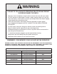
WARNING FAILURE TO FOLLOW SAFE OPERATING PRACTICES MAY RESULT IN SERIOUS INJURY OR DEATH. • Read this manual completely as well as other manuals that came with your mower. • DO NOT operate on steep slopes. To check a slope, attempt to back up it (with the cutter deck down). If the machine can back up the slope without the wheels slipping, reduce speed and use extreme caution. • Under no circumstances should the machine be operated on slopes greater than 15 degrees (20 degrees for SVR).
Table of Contents R Table of Contents SECTION 1 - GENERAL INFORMATION. ..................................................................................1 1.1 Introduction............................................................................................................................................1 1.2 Direction Reference............................................................................................................................1 1.3 Servicing ThIS ACCESSORY....................
Section 1 R GENERAL INFORMATION 1.1 Introduction 1.2 Direction Reference Your OCDC was built to the highest standards in the industry. However, the prolonged life and maximum efficiency of your OCDC depends on you following the installation and operation instructions in this manual. The “Right” and “Left”, “Front” and “Rear” of the machine are referenced from the operator’s right and left when seated in the normal operating position and facing the forward travel direction.
Section 1 R 1.
Section 2 R SAFETY INFORMATION 2.1 Introduction Danger Your mower is only as safe as the operator. Carelessness or operator error may result in serious bodily injury or death. Hazard control and accident prevention are dependent upon the awareness, concern, prudence, and proper training of the personnel involved in the operation, transport, maintenance and storage of the equipment. Make sure every operator is properly trained and thoroughly familiar with all of the controls before operating the mower.
Section 2 R 2.4 OCDC Operation 2. When using any attachment, never direct the discharge of material toward bystanders or allow anyone near the machine while in operation. The OCDC (Operator Controlled Discharge Chute) can be raised or lowered to side discharge or block the discharge of grass clippings. Follow the steps below for proper operation of the OCDC. 3.
Section 2 R OPEN POSITION In the open position, the clippings will side discharge. 1. Rotate OCDC control handle outward to lower the side discharge chute. See Figure 2-2. The discharge chute will lower to it's original position for safe sidedischarge operation. Figure 2-2.
Section 3 R INSTALLATION INSTRUCTIONS 3.1 SCZ/STC-48V Block-off plate installation instruction 7. Install the rear hinge bracket to the cutter deck using one (1) 5/16-18 x 1" bolt, one (1) 5/16" flatwasher and one (1) 5/16-18 elastic stop nut. Do not tighten the hardware. See Figure 3-3. Prepare the machine so there is easy and safe access to the work area. Park the machine on a flat, level surface and apply the parking brake.
Section 3 R *Template *48V Template DO NOT Drill Hole Center Punch & Drill 11/32” Hole Template Discharge Chute Mounting Rail Center Punch & Drill 11/32” Hole A = 0.40” (48V) B = 3” (48V) C = 3-3/4” (48V) A C B Figure 3-4.
Section 3 R 16. Install the front hinge bracket to the cutter deck using two (2) 5/16-18 x 3/4" bolts and two (2) 5/16-18 elastic stop nuts. See Figure 3-3, page 6. Do not tighten the hardware. OCDC Pivot Bracket 17. Install the block off plate weldment to the front and rear hinge brackets using two (2) 5/16-18 x 3-1/2" bolts and two (2) 5/16-18 elastic stop nuts. See Figure 3-5. Do not tighten the bolts completely. Secure the hardware so the block off plate weldment moves freely.
Section 3 R 3.2 SCZ-52 & STC-52V/61v Block-off plate installation instruction 7. Install the rear hinge bracket to the cutter deck using one (1) 5/16-18 x 1" bolt, one (1) 5/16" flatwasher and one (1) 5/16-18 elastic stop nut. Do not tighten the hardware. See Figure 3-9. Prepare the machine so there is easy and safe access to the work area. Park the machine on a flat, level surface and apply the parking brake. Remove the ignition key and disconnect the positive and negative cables from the battery.
Section 3 R *Template *52V Template *61V Template Center Punch & Drill 11/32” Hole Template Discharge Chute Mounting Rail Center Punch & Drill 11/32” Hole A C B A = 0.40” (All Deck Sizes) B = 3-3/4” (52V, 61V) C = 4-1/2” (52V, 61V) Figure 3-10.
Section 3 R 16. Install the front hinge bracket to the cutter deck using two (2) 5/16-18 x 3/4" bolts and two (2) 5/16-18 elastic stop nuts. See Figure 3-9, page 9. Do not tighten the hardware. OCDC Pivot Bracket 17. Install the block off plate weldment to the front and rear hinge brackets using two (2) 5/16-18 x 3-1/2" bolts and two (2) 5/16-18 elastic stop nuts. See Figure 3-11. Do not tighten the bolts completely. Secure the hardware so the block off plate weldment moves freely.
Section 3 R 3.3 SCZ-48V/52v & STC-48V/52V/61V Control handle installation 3. For SCZ 48V-OCDC, remove and discard two (2) 5/16-18 serrated flange nuts and two (2) 5/16-18 x 3/4" carriage bolts used to secure the right hand fuel tank mounting bracket to machine frame. See Figure 3-15. - NOTE Refer to Step #1 for STC-OCDC Proceed to Step #3 for SCZ 48V-OCDC SCZ Right Side Fuel Tank 1. For STC-OCDC, use a 11/32" (.343) drill bit to enlarge the holes on the right rear fuel tank mounting bracket.
Section 3 R Upper Control Link Spacer (61V Only) A A B B OCDC Discharge Chute OCDC Control Rod Figure 3-18. OCDC Discharge Chute Installation Figure 3-17. OCDC Control Lever Installation 8. Tighten the hardware. 9. Install the OCDC discharge chute to the cutter deck. Secure using two (2) 5/16-18 x 1-3/4" bolt and two (2) 5/16-18 elastic stop nuts. See Figure 3-18. 10. Tighten the hardware. 11.
Section 3 R 3.4 SCZ-61V & STT-52V/61V Block-Off 7. Install the rear hinge bracket to the cutter deck using one (1) 5/16-18 x 1" bolt, one (1) 5/16" flatwasher and one (1) 5/16-18 elastic stop nut. Do not tighten the hardware. See Figure 3-21. Plate iNSTALLATION INSTRUCTION Prepare the machine so there is easy and safe access to the work area. Park the machine on a flat, level surface and apply the parking brake. Remove the ignition key and disconnect the positive and negative cables from the battery.
Section 3 R *Template *STT-52V Template *61V Template Center Punch & Drill 11/32” Hole Template Discharge Chute Mounting Rail Center Punch & Drill 11/32” Hole A C B A = 0.40” (All Deck Sizes) B = 3-3/4” (52V, 61V) C = 4-1/2” (52V, 61V) Figure 3-22.
Section 3 R 16. Install the front hinge bracket to the cutter deck using two (2) 5/16-18 x 3/4" bolts and two (2) 5/16-18 elastic stop nuts. See Figure 3-21, page 14. Do not tighten the hardware. OCDC Pivot Bracket 17. Install the block off plate weldment to the front and rear hinge brackets using two (2) 5/16-18 x 3-1/2" bolts and two (2) 5/16-18 elastic stop nuts. See Figure 3-23. Do not tighten the bolts completely. Secure the hardware so the block off plate weldment moves freely.
Section 3 R 3.5 SCZ-61V & STT-52V/61V Control handle installation 4. Install the jam nut and the OCDC handle knob to the control rod. See Figure 3-27. Tighten the jam nut. 5. Secure the lower control link to the block off plate weldment using one (1) 5/16-18 x 1-1/2" bolt (one spacer for STC-61V cutter decks) and one (1) 5/1618 elastic stop nut. See Figure 3-24, Page 16. - NOTE Refer to Step #1 for SCZ-61V-OCDC Proceed to Step #13, Page 18 for STT-52V/61V-OCDC 1.
Section 3 R 13. For STT-52V/61V-OCDC, position the OCDC handle bracket on the right side fender and align as shown in Figure 3-29. 12. An adjustment may need to be made to the lower control link to insure smooth operation. If the OCDC is difficult to lock in the closed position, shorten the lower control link slightly until the OCDC locks smoothly into the closed position. 14. Using the OCDC handle bracket as a guide, mark the mounting holes in the fender.
Section 3 R 17. Install the jam nut and the OCDC handle knob to the control rod. See Figure 3-31. Tighten the jam nut. 24. Operate the OCDC checking for proper operation as outlined in Section 2.4, pages 4 and 5. 18. Secure the lower control link to the block off plate weldment using one (1) 5/16-18 x 1-1/2" bolt, one spacer and one (1) 5/16-18 elastic stop nut. See Figure 3-24, Page 16. 25. An adjustment may need to be made to the lower control link to insure smooth operation.
Section 3 R 3.6 SVR-48V/52V/61V Block-off plate installation instruction 7. Install the rear hinge bracket to the cutter deck using one (1) 5/16-18 x 1" bolt, one (1) 5/16" flatwasher and one (1) 5/16-18 elastic stop nut. Do not tighten the hardware. See Figure 3-35. Prepare the machine so there is easy and safe access to the work area. Park the machine on a flat, level surface and apply the parking brake. Remove the ignition key and disconnect the positive and negative cables from the battery.
Section 3 R *Template *48V Template *52V Template *61V Template Center Punch & Drill 11/32” Hole Template Discharge Chute Mounting Rail Center Punch & Drill 11/32” Hole A C B A = 0.40” (All Deck Sizes) B = 3” (48V) 3-3/4” (52V, 61V) C = 3-3/4” (48V) 4-1/2” (52V, 61V) Figure 3-36.
Section 3 R 16. Install the front hinge bracket to the cutter deck using two (2) 5/16-18 x 3/4" bolts and two (2) 5/16-18 elastic stop nuts. See Figure 3-35, Page 20. Do not tighten the hardware. OCDC Pivot Bracket 17. Install the block off plate weldment to the front and rear hinge brackets using two (2)5/16-18 x 3-1/2" bolts and two (2) 5/16-18 elastic stop nuts. See Figure 3-37. Do not over tighten the bolts completely. Secure the hardware so the block off plate weldment moves freely.
Section 3 R 3.7 SVR-48V/52V/61V Control handle installation 1. Remove and retain two (2) 1/4-20 serrated flange nuts used to secure the neutral switch bracket to machine frame. See Figure 3-39. SVR-OCDC Handle Bracket SVR-OCDC Control Rod 1/4-20 Serr Flange Neutral Switch Bracket Figure 3-39. SVR OCDC Handle Bracket Install 2. Install the OCDC handle bracket to the machine frame and neutral switch bracket. Secure using two (2) 1/4-20 serrated flange nuts removed in the previous step. See Figure 3-39.
Section 3 R Upper Control Link Spacer (61V Only) A A B B OCDC Discharge Chute Figure 3-41.
Section 8 R ILLUSTRATED PARTS LIST 4.1 SCAG APPROVED ATTACHMENTS AND ACCESSORIES. Attachments and accessories manufactured by companies other than Scag Power Equipment are not approved for use on this machine.
Section 8 R STC/SCZ/STT/SVR - OCDC 1 4 2 3 5 6 7 10 35 9 37 12 8 34 9 14 6 9 36 16 15 12 9 17 A 18 19 38 B 7 17 7 A 25 9 22 12 30 9 9 31 12 26 7 B 29 33 7 9 9 9 6 13 21 20 9 14 6 23 32 9 9 9 24 25 28 27 26 20
Section 8 R STC/SCZ/STT/SVR - OCDC Ref. No. 1 2 3 4 5 6 7 8 9 10 11 12 13 14 15 16 17 18 19 20 21 22 23 24 25 26 27 28 29 Part No.
Section 8 R STC/SCZ/STT/SVR - OCDC Ref. No. 30 31 32 33 34 35 36 37 38 Part No.
LIMITED WARRANTY- COMMERCIAL ACCESSORY Any part of the Scag commercial accessory manufactured by Scag and found, in the reasonable judgment of Scag, to be defective in material or workmanship, will be repaired or replaced by an Authorized Scag Service Dealer without charge for parts and labor. The Scag accessory, including any defective part, must be returned to an Authorized Scag Service Dealer within the warranty period.