
Operator`s manual


14
R
Section 3
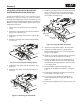
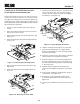
Install the rear hinge bracket to the cutter deck using 7.
one (1) 5/16-18 x 1" bolt, one (1) 5/16" flatwasher
and one (1) 5/16-18 elastic stop nut. Do not tighten
the hardware. See Figure 3-21.
Rear Hinge
Bracket
Front Hinge
Bracket
Hinge Weldment InstallationFigure 3-21.
Hold the rear hinge bracket tight to the cutter deck.8.
Using the rear hinge bracket as a guide, drill the 9.
bottom mounting bolt hole for the rear hinge bracket
using an 11/32" drill bit.
Install one (1) 5/16-18 x 3/4" bolt and one (1)5/16-18 10.
elastic stop nut. Do not tighten the hardware.
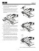
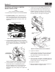
Install the template to locate the mounting holes for 11.
the lever assembly. Secure to the cutter deck using
the turbo baffle mounting hardware removed in step
3. See Figure 3-22.
Hold the template against the discharge chute 12.
mounting rail and tighten the hardware. See Figure
3-22.
Center punch and drill the mounting holes using an 13.
11/32" drill bit. See Figure 3-22.
Carefully lay out the remaining mounting holes 14.
for the front hinge bracket in the cutter deck. See
Figure 3-22.
Center punch and drill the holes using an 11/32" drill 15.
bit.
SCZ-61V & STT-52V/61V3.4 BLOCK-OFF
PLATE INSTALLATION INSTRUCTION
Prepare the machine so there is easy and safe access to
the work area. Park the machine on a flat, level surface
and apply the parking brake. Remove the ignition key
and disconnect the positive and negative cables from the
battery. Maintain all safety related work procedures. Always
wear hand and eye protection.
Lift the rear of the machine and secure with jack 1.
stands.
Remove the right side drive tire from the machine to 2.
gain access to the work area.
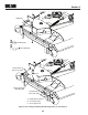
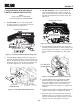
Remove the discharge chute from the machine. See 3.
Figure 3-19.
Retain the discharge chute and mounting hardware 4.
for future use.
Remove &
Retain
Removing the Discharge ChuteFigure 3-19.
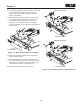
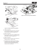
Remove the turbo baffle from the cutter deck. See 5.
Figure 3-20.
Retain the turbo baffle and mounting hardware for 6.
future use.
Remove &
Retain
Removing the Turbo BaffleFigure 3-20.