OPERATOR’S MANUAL Cheetah Models: SCZ48V-22FX SCZ48V-23CV SCZ48V-23CV-EFI SCZ48V-26BS SCZ52V-23FX SCZ52V-25CV SCZ52V-25CV-EFI SCZ52V-26BS Congratulations on owning a Scag mower! This manual contains the operating instructions and safety information for your Scag mower. Reading this manual can provide you with assistance in maintenance and adjustment procedures to keep your mower performing to maximum efficiency. The specific models that this book covers are listed on the inside cover.
WARNING FAILURE TO FOLLOW SAFE OPERATING PRACTICES MAY RESULT IN SERIOUS INJURY OR DEATH. • Read this manual completely as well as other manuals that came with your mower. • DO NOT operate on steep slopes. To check a slope, attempt to back up it (with the cutter deck down). If the machine can back up the slope without the wheels slipping, reduce speed and use extreme caution. • Under no circumstances should the machine be operated on slopes greater than 15 degrees.
Table of Contents R Table of Contents SECTION 1 - GENERAL INFORMATION. ..................................................................................1 1.1 Introduction............................................................................................................................................1 1.2 Direction Reference............................................................................................................................1 1.
Table of Contents R SECTION 5 - TROUBLESHOOTING CUTTING CONDITIONS................................................20 SECTION 6 - ADJUSTMENTS..................................................................................................23 6.1 Parking Brake Adjustment.............................................................................................................23 6.2 Travel Adjustments...........................................................................................................
Table of Contents R SCZ EFI ELECTRICAL SYSTEM......................................................................................................................70 REPLACEMENT DECALS AND INFORMATION PLATES..............................................................................72 SCZ ELECTRICAL SCHEMATIC......................................................................................................................74 LIMITED WARRANTY - COMMERCIAL EQUIPMENT......................................
Table of Contents R IV
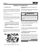
Section 1 R GENERAL INFORMATION 1.1 Introduction USE ONLY SCAG APPROVED ATTACHMENTS AND ACCESSORIES. Your mower was built to the highest standards in the industry. However, the prolonged life and maximum efficiency of your mower depends on you following the operating, maintenance and adjustment instructions in this manual. Attachments and accessories manufactured by companies other than Scag Power Equipment are not approved for use on this machine. See Section 8-1.
Section 1 R 1.
Section 2 R SAFETY INFORMATION 2.1 Introduction Danger Your mower is only as safe as the operator. Carelessness or operator error may result in serious bodily injury or death. Hazard control and accident prevention are dependent upon the awareness, concern, prudence, and proper training of the personnel involved in the operation, transport, maintenance and storage of the equipment. Make sure every operator is properly trained and thoroughly familiar with all of the controls before operating the mower.
Section 2 R 3. DO NOT allow children to ride or play on the machine, it is not a toy. 10. Be sure the interlock switches are functioning correctly. 4. Clear the area to be mowed of objects that could be picked up and thrown by the cutter blades. 11. Fuel is flammable; handle it with care. Fill the fuel tank outdoors. Never fill it indoors. Use a funnel or spout to prevent spillage. Clean up any spillage before starting the engine. 5. DO NOT carry passengers. 6.
Section 2 R 2. Reduce speed and exercise extreme caution on slopes and in sharp turns to prevent tipping or loss of control. Be especially cautious when changing directions on slopes. 14. NEVER raise the deck with the blades engaged. 15. Take all possible precautions when leaving the machine unattended, such as disengaging the mower, lowering the attachments, setting the parking brake, stopping the engine, and removing the key. 3.
Section 2 R 23. Use care when approaching blind corners, shrubs, trees, or other objects that may obscure vision. This mower has been designed for good traction and stability under normal mowing conditions. However, caution must be used when traveling on slopes, especially when the grass is wet. Do not mow on wet grass. Wet grass reduces traction and steering control. 24. NEVER leave the machine running unattended. 2.
Section 2 R 1. To lower the roll bar, remove the hairpin cotter pins and remove the two (2) lock pins. See Figure 2-1. 2. Lower the roll bar to the folded position. See Figure 2-1. 3. To raise the roll bar, lift the bar to the upright position. 20 o 15 o 10 o 5o 4. Install the two (2) lock pins through the holes and secure with the two (2) hairpin cotter pins. See Figure 2-1. Figure 2-2.
Section 2 R 2.6 Maintenance Considerations & Storage WARNING 1. Never make adjustments to the machine with the engine running unless specifically instructed to do so. If the engine is running, keep hands, feet, and clothing away from moving parts. Hydraulic fluid is under high pressure and can penetrate skin causing injury. If hydraulic fluid is injected into the skin, it must be surgically removed within a few hours by a doctor or gangrene may result. 2.
Section 2 R 2.9 Safety And Instructional Decals FORWARD F R REvERSE 482100 483407 483407 483406 483425 Avoid injury from burns - Shut off engine - Allow to cool several minutes - Remove cap slowly - Do not overfill EPACentroRLP / Q-08-027A 484377 483300 Molded in Fuel Tank 483444 WARNING 484180 INSTALL BELT COvER BEFORE OPERATING MACHINE READ OPERATOR'S MANUAL 483402 483402 Flat Free WARNING Operation of this equipment may create sparks that can start fires around dry vegetation.
Section 3 R SPECIFICATIONS 3.1 Engine General Type.................................................................................................Heavy Duty Industrial/Commercial Gasoline Engine Model: Scag Model SCZ48V-22FX..............................................................................................................Kawasaki FX691V Scag Model SCZ48V-23CV.....................................................................................................................
Section 3 R Parking Brake........................................................... Foot Pedal Actuated Linkage to Brakes on Both Drive Wheel Axles Wheels: (2) Front Caster - ...........................................................................................................................................13 X 6.50 (2) Drive - ............................................................................ 23 X 9.5-12 Four-Ply Pneumatic Tubeless, Radius Edge Tire Pressure: Front Caster................
Section 4 R OPERATING INSTRUCTIONS 2. Mower Deck Switch (Figure 4-1). Used to engage and disengage the mower drive system. Pulling up on the switch will engage the deck drive. Pushing down on the switch will disengage the deck drive. CAUTION Do not attempt to operate this mower unless you have read this manual. Learn the location and purpose of all controls and instruments before you operate this mower. 3. Engine Choke Control (Figure 4-1). Used to start a cold engine. 4.
Section 4 R 6. Hourmeter (Figure 4-1). Indicates the number of hours the engine has been operated. It only operates when the engine is running. Has preset maintenance reminders for engine and hydraulic system oil changes. Will start flashing scheduled maintenance 2 hours before preset time and continue flashing until 2 hours after. Automatically resets. 7. Fuse Holders (Figure 4-1). Two 20-amp fuses protect the mower’s electrical system.
Section 4 R 17. Suspension Control Lever (Figure 4-1). Used to select the optimum suspension rate based on the operator. 5. Check interlock system for proper operation. (See Section 4.2.) 6. Check tire pressure. Adjust pressure if necessary. (See Section 7.10.) 18. Seat Belt (Figure 4-1). Used to secure the operator. Seat belt must be worn at all times when the ROPS is in the upright and locked position. 4.4 Starting The Engine 19. Seat Hold Down Release Latch (Figure 4-1). Located behind the seat.
Section 4 R Reverse Travel Learn the operation on flat ground before operating on slopes. Start practicing with a slow engine speed and slow forward travel. Caution Learn to feather the steering controls to obtain a smooth operating action. Disengage power to the mower before backing up. Do not mow in reverse unless absolutely necessary and then only after observation of the entire area behind the mower.
Section 4 R 4.6 Engaging The Deck Drive (Cutter Blades) 4.7 Hillside Operation WARNING 1. Set the throttle at about 3/4 speed. Do not attempt to engage the deck drive at high speed as this shortens the electric clutch life — use only moderate engine speed when engaging the deck drive. DO NOT operate on steep slopes. To check a slope, attempt to back up it (with the cutter deck down). If the machine can back up the slope without the wheels slipping, reduce speed and use extreme caution.
Section 4 R 4.9 After Operation 4.11 Moving Mower With Engine Stopped 1. Wash the entire mower after each use. Do not use high pressure spray or direct the spray onto electrical components. To “free-wheel” or move the mower around without the engine running, move the dump valve control levers back and towards the engine. See Figure 4-6. Disengage the parking brake and move the mower by hand. When the machine is in the desired position, engage the parking brake and forward until they stop.
Section 4 R 5. When mowing wet or tall grass, mow the grass twice. Raise the mower to the highest setting for the first pass and then make a second pass to the desired height. 3. Insert the lanyard pin into the cutting height index at the desired cutting height. Push forward on the deck lift foot lever, hold in place and pull back on the deck release lever. See Figure 4-8. Slowly release the foot pedal.
Section 4 R 4.15 adjusting the Operator suspension platform The operator suspension platform can be adjusted to optimize operator comfor t and ride. Adjust the suspension rate by moving the suspension control lever down to increase (stiffen) or up to decrease (soften) the suspension shock rate. See Figure 4-10. SUSPENSION CONTROL LEVER Figure 4-10. Operator Suspension Platform Adjustment 4.16 Towing (Optional Hitch Accessory) 1. NEVER allow children or others in or on towed equipment. 2.
Section 5 R TROUBLESHOOTING CUTTING CONDITIONS Condition Cause Stringers - Occasional Low engine RPM Blades of Uncut Grass Width of Deck SGB020 Cure Run engine at full RPM Ground speed too fast Slow speed to adjust for conditions Wet grass Cut grass after it has dried out Dull blades, incorrect sharpening Sharpen blades Deck plugged, grass accumulation Clean underside of deck Belts slipping Adjust belt tension Streaking - Strips of Dull, worn blades Uncut Grass in Cutting Path Incorrect bla
Section 5 R TROUBLESHOOTING CUTTING CONDITIONS (CONT'D) Condition Cause U ne v en C ut on F lat Lift worn from blade Ground - Wavy High-Low Appearance, Scalloped Blade upside down Cut, or Rough Contour Cure Replace blade Mount with cutting edge toward ground Deck plugged, grass accumulation Clean underside of deck Too much blade angle (deck pitch) Adjust pitch and level Deck mounted improperly See your authorized SCAG dealer Bent spindle area See your authorized SCAG dealer Dull blade Sharpen
Section 5 R TROUBLESHOOTING CUTTING CONDITIONS (CONT'D) Condition Cause Scalping - Blades Hitting Low tire pressures Dirt or Cutting Very Close to the Ground Ground speed too fast Width of Deck Cure Check and adjust pressures Slow speed to adjust for conditions Cutting too low May need to reduce ground speed, raise cutting height, change direction of cut, and/or change pitch and level Rough terrain May need to reduce ground speed, raise cutting height, and/or change direction of cut Ground speed
Section 6 R ADJUSTMENTS 6.1 Parking Brake Adjustment WARNING PULL BACK ON PARKING BRAKE LATCH Do not operate the mower if the parking brake is not operable. Possible severe injury could result. PUSH BRAKE PEDAL FORWARD The parking brake linkage should be adjusted whenever the parking brake lock latch is placed in the “ENGAGE” position and the parking brake will not prevent the mower from moving.
Section 6 R B. The steering control levers are in the full forward position and the mower pulls to one side or the other when traveling in a forward direction. (Tracking Adjustment). 5. Tighten the jam nuts and repeat for the LH wheel. See Figure 6-3. 6. Actuate the steering control levers forward and reverse several times and return them to the neutral position. Neutral Adjustment 7. Check that the drive wheels remained in neutral and readjust if necessary. 1.
Section 6 R 6.4 Belt Adjustment 2. If at full speed the mower pulls left, it is an indication that the right wheel is turning faster than the left wheel. To adjust this condition, proceed as follows: WARNING A. Stop the machine and place the steering control levers in the neutral position. Turn the tracking adjustment bolt for the RH pump inward (clockwise). This will cause the control rod to stroke the RH pump less, slowing down the RH wheel. See Figure 6-4.
Section 6 R Cutter Deck Level from the top of the cutter deck to the floor at the front RH side of the cutter deck directly in front of the cutter deck hanging chains. The measurement at the front of the cutter deck should be the same as the rear of the deck. Make these measurements at the LH side of the cutter deck also.
Section 6 R 1. Check the cutter deck cutting height by placing the lanyard pin in the 4-1/2" position on the cutting height index. Release the deck from the transport position and allow the deck to move to the 4-1/2" cutting height position. B. 4" (factory setting), 4-1/4" or 4-1/2" Position - (See Figure 6-8). For general purpose cutting. This gives the best mix of cutting performance in all types of grass. C. 4-3/4" or 5-1/4" Position - (See Figure 6-8).
Section 6 R 1 2 3 4 A B 1 2 34 A B Custom-Cut Baffle Adjustment Mounting Slot Selected Slot “A” Height (inches) Hole 1 3-3/4” Slot “B” Height (inches) Mounting Hardware Location Hole 2 Hole 3 Hole 4 4-1/4” 4-3/4” 5-1/4” Hole 2 3-1/2” Hole 3 4” Figure 6-8.
Section 6 R 6.8 ADJUSTING THE STEERING DAMPNERS INSPECTION WINDOW (x3) The steering dampner adjustment can be made to increase or decrease the dampening affect for smooth, precise steering control. There are three locations on the steering control levers that allow the operator to adjust the dampening affect of the steering control based on cutting conditions. 1. Top Mounting Location (Figure 6-9). Used for the highest dampening affect on the steering controls. Figure 6-10. Clutch Air Gap Adjustment 1.
Section 7 R MAINTENANCE 7.1 Maintenance Chart - Recommended Service Intervals HOURS Break-In (First 10) 8 20 40 100 200 Procedure 500 Comments X Check all hardware for tightness X Check hydraulic oil level X C h e c k a l l b e l t s f o r p r o p e r See paragraph 7.8 alignment X Change engine oil and filter See paragraph 7.3 See paragraph 7.4 X Check hydraulic fittings and hoses Use extreme caution when for leaks checking the hydraulic hoses. See paragraph 2.
Section 7 R MAINTENANCE CHART - RECOMMENDED SERVICE INTERVALS (CONT'D) HOURS Break-In (First 10) 8 40 100 200 Procedure 500 Comments X Apply grease to fittings See paragraph 7.2 X Check hardware for tightness X Change engine oil filter See paragraph 7.4 X Check hydraulic oil level See paragraph 7.3 X Replace engine fuel filter See paragraph 7.5 X Drain hydraulic system and Use SAE 20W50 Motor Oil. replace hydraulic oil See paragraph 7.
Section 7 R GREASE FITTING LUBRICATION Lubricant Interval Lithium MP White Grease 2125 (40 Hours/Weekly) Chassis Grease (100 Hours/Bi-monthly) Chassis Grease (200 Hours/Monthly) Chassis Grease (500 Hours/Yearly) 4 1 5 2 3 1 5 2 3 4 Figure 7-1.
Section 7 R 7.3 Hydraulic System - IMPORTANT The hydraulic oil should be changed if you notice the presence of water or a rancid odor to the hydraulic oil. A. Checking Hydraulic Oil Level The hydraulic oil level should be checked after the first 10 hours of operation. Thereafter, check the oil after every 200 hours of machine operation or monthly, whichever occurs first. 1. Park the mower on a level surface and stop the engine. 2.
Section 7 R 6. Reinstall the filter guards and torque the screws to 65 in/lbs. DUMP VALVE CONTROL LEVER 7. Remove the top port plug from both axles before filling with oil. See Figure 7-4. DUMP VALVE CONTROL LEVER "FREEWHEEL" POSITION "FREEWHEEL" POSITION 2012 SCZ48 52 DVL Figure 7-5. Dump Valve Control Lever 12. While in the operator's position, start the engine and disengage the parking brake. 13.
Section 7 R A. Checking Engine Crankcase Oil Level FILLER NECK INSERT 1/2 . 1/4 . . . E The engine oil level should be checked after every 8 hours of operation or daily as instructed in the Engine Operator’s Manual furnished with this mower. .3/4 F FUEL LEVEL B. Changing Engine Crankcase Oil After the first 20 hours of operation, change the engine crankcase oil and replace the oil filter.
Section 7 R B. Replacing In-Line Fuel Filter Elements 2. Remove the air cleaner and inspect. 3. Clean or replace the air cleaner and foam pre-cleaner as recommended by the engine manufacturer. The engine fuel filter should be replaced after every 500 hours of operation or annually, whichever occurs first. See Figure 7-8. 4. Replace the air cleaner cover and be sure to snap the two latches closed. 1. Close the shut-off valve. AIR FILTER ASSEMBLY 2. Remove and replace the engine fuel filter.
Section 7 R WARNING WARNING BATTERIES PRODUCE EXPLOSIVE GASES. Charge the battery in a well ventilated space so gases produced while charging can dissipate. Electric storage battery fluid contains sulfuric acid which is POISON and can cause SEVERE CHEMICAL BURNS. Avoid contact of fluid with eyes, skin, or clothing. Use proper protective gear when handling batteries. DO NOT tip any battery beyond 45° angle in any direction. If fluid contact does occur, follow first aid suggestions below.
Section 7 R 7.9 Cutter Blades - NOTE - A. Blade Inspection DO NOT sharpen the blades beyond 1/3 of the width of the blade. See Figure 7-10. 1. Sharpen the cutting edge at the same bevel as the original. See Figure 7-10. Sharpen only the top of the cutting edge to maintain sharpness. 1. Remove the ignition key before servicing the blades. 2. Raise the mower deck to the highest position. Place the lanyard pin in the highest cutting height position to prevent the cutter deck from falling.
Section 7 R toward the top. Caution 5. Install the spacer onto the blade bolt and insert the bolt into the cutter spindle shaft. Inspect the cutter blade spacer(s) and washer for wear and/or cupping. Replace the worn parts. Worn spacer(s) and/or washer will not allow proper tightening of the cutter blade and can lead to cutter blade failure, personal injury or property damage. 6. Install the hex nut to the blade bolt at the top of the cutter spindle.
Section 8 R ILLUSTRATED PARTS LIST 8.1 Scag Approved Attachments And Accessories Attachments and accessories manufactured by companies other than Scag Power Equipment are not approved for use on this machine.
Section 8 R 41
Section 8 R 48V & 52V CUTTER DECKS 2 3 4 9 5 9 11 75 13 2 3 11 4 12 8 16 13 72 69 66 13 17 25 24 23 24 67 30 83 25 25 82 26 81 27 71 80 76 58 62 63 19 22 78 70 29 63 64 18 13 20 15 21 17 68 5 6 9 11 14 73 65 2 3 10 74 29 10 11 4 7 1 9 79 77 29 57 30 59 29 61 56 28 30 25 60 31 32 54 53 46 43 44 45 33 34 36 9 47 48 35 37 38 49 39 50 34 51 52 42 41 40 42
Section 8 R 48V & 52V CUTTER DECKS Ref. No. 1 2 3 4 5 6 7 8 9 10 11 Part No.
Section 8 R CUTTER DECK CONTROLS 2 1 37 34 3 5 35 4 7 38 31 33 34 32 36 29 30 9 28 8 6 11 10 25 27 24 15 12 23 13 15 19 13 15 16 17 18 16 14 17 15 18 19 18 15 CUTTER DECK 44 15 15 20 21 18 22
Section 8 R CUTTER DECK CONTROLS Ref. No. Part No.
Section 8 R SHEET METAL COMPONENTS 1 6 5 72 8 12 13 50 A 4 9 10 11 11 54 3 15 16 48 13 47 13 21 13 30 52 53 54 51 17 17 18 23 53 22 19 A 49 19 20 11 24 21 46 45 22 30 19 19 13 24 19 31 26 33 34 44 35 35 25 19 26 27 28 37 32 36 42 39 38 41 43 42 40 46 29
Section 8 R SHEET METAL COMPONENTS Ref. No. 1 2 3 4 5 6 7 8 9 10 11 12 13 14 15 16 17 18 19 20 21 22 23 24 25 26 27 28 29 30 31 32 33 34 35 36 37 38 39 40 41 42 43 44 45 Part No.
Section 8 R SCZ ROLL-OVER PROTECTION SYSTEM 2 1 3 6 2 4 7 2 5 7 12 32 5 1 13 10 9 12 9 10 9 12 9 11 9 12 9 12 12 8 8 10 8 48 6 1 14 10 9 10 9 11 10 11 4 10 11
Section 8 R SCZ ROLL-OVER PROTECTION SYSTEM Ref. No. 1 2 3 4 5 6 7 8 9 10 11 12 13 14 Part No. 462414 484168 484170 484169 484167 04001-90 04021-07 04001-145 04021-19 04040-13 04001-70 484527 425962 425961 Description ROPS Assembly, Foldable Pin Assembly (incl. #3) Spring, ROPS Clip, ROPS Spring, ROPS Anti-Rattle Bolt, Hex Head 1/2-13 x 3-1/4” Nut, Elastic Stop 1/2-13 Bolt, Hex Head 1/2-13 x 3-1/2” Nut, Center Lock 1/2-13 Flatwasher, 1/2-.562 x 1.375 x .
Section 8 R SCZ SEAT ASSEMBLY 5 4 3 3 1 3 2 6 3 7 3 8 Ref. No. 1 2 3 4 5 6 7 8 Part No.
Section 8 R NOTES 51
Section 8 R SCZ SUSPENSION SYSTEM 9 2 4 3 11 4 1 10 8 E 3 5 12 7 6 16 13 8 14 E 19 17 15 15 18 21 22 21 8 A 30 78 A 8 7 B 42 45 44 12 20 20 39 8 41 38 37 23 46 19 12 12 48 49 21 C 26 47 22 23 B 31 32 23 15 25 8 43 24 24 27 28 23 D 33 36 43 C 28 36 34 35 40 20 20 12 50 34 19 41 34 D 26 4 8 29 41 20 52 34
Section 8 R SCZ SUSPENSION SYSTEM Ref. No. 1 2 3 4 5 6 7 8 9 10 11 12 13 14 15 16 17 18 19 20 21 22 23 24 25 26 Part No. 484588 483559 04001-59 04019-02 43606 04001-45 04041-07 04021-09 483371 452143 04001-100 04019-03 452147 462262 484148 04001-46 04001-08 425566 452152 04001-09 04001-20 04030-04 43086 484035 425257 484201 Ref. No.
Section 8 R SCZ STEERING COMPONENTS 2 1 4 11 17 9 10 3 6 5 A 12 13 14 18 11 14 17 17 15 27 33 32 9 31 24 12 A 33 27 To Transaxle 30 7 16 29 21 25 23 17 20 21 12 17 19 22 23 17 17 8 26 28 54
Section 8 R SCZ STEERING COMPONENTS Ref. No. 1 2 3 4 5 6 7 8 9 10 11 12 13 14 15 16 17 18 19 20 21 22 23 24 25 26 27 28 29 30 31 32 33 Part No.
Section 8 R SCZ DRIVE SYSTEM COMPONENTS 1 2 3 5 31 8 7 6 28 6 4 9 1 3 6 10 5 6 11 27 30 7 11 7 26 14 13 12 14 26 30 11 20 A 15 16 17 25 22 29 24 21 21 29 19 23 A 20 22 18 56
Section 8 R SCZ DRIVE SYSTEM COMPONENTS Ref. No. 1 2 3 4 5 6 7 8 9 10 11 12 13 14 15 16 17 18 19 20 21 22 23 24 25 26 27 28 29 30 31 Part No.
Section 8 R SCZ BRAKE COMPONENTS 1 2 6 4 A 29 3 7 4 5 8 3 10 37 24 11 9 8 38 12 6 36 A 35 17 13 6 15 14 1 16 18 18 19 20 27 27 34 30 28 6 29 32 35 31 23 21 22 2 24 26 25 33 58 18
Section 8 R SCZ BRAKE COMPONENTS Ref. No. 1 2 3 4 5 6 7 8 9 10 11 12 13 14 15 16 17 18 19 20 21 22 23 24 25 26 27 28 29 30 31 32 33 34 35 36 37 38 Part No.
Section 8 R SCZ HYDRAULIC SYSTEM 3 2 4 1 C 2 2 7 5 8 3 6 13 A B 13 C 8 9 10 A 11 B 26 25 17 12 15 18 19 18 16 24 20 11 14 21 22 28 23 27 21 25 24 26 60
Section 8 R SCZ HYDRAULIC SYSTEM Ref. No. 1 2 3 4 5 6 7 8 9 10 11 12 13 14 15 16 17 18 19 20 21 22 23 24 25 26 27 28 Part No. 425861 04003-02 04017-04 483514 484517 425860 484196 04117-03 04021-08 484607 48136-13 484537 48136-05 482800-04 HG44133 484573 04040-14 482070 44186 04062-02 43876 484454 04041-07 04030-04 04001-46 43864 484455 Description Cover, Oil Reservoir Bolt, Carriage 1/4-20 x 3/4” Bolt, Serrated Flange 1/4-20 x 1/2” Cap, Oil Reservoir Oil Reservoir Assembly (incl.
Section 8 R SCZ FUEL SYSTEM 1 3 2 8 12 12 10 11 4 5 6 13 14 9 10 18 7 15 21 18 18 22 TO ENGINE 18 20 18 19 10 18 4 62 10 15 16 3 17 10 11 10 22 23 To Engine Purge Port 11 11 10 11 10 14 12 1 13 12 8 9 7 2
Section 8 R SCZ FUEL SYSTEM Ref. No. 1 2 3 4 5 6 7 8 9 10 11 12 13 14 15 16 17 18 19 20 21 22 23 Part No. 484286 484297 484279-01 484323 484242 462445 484553 482571 484333 484285 48059-15 484345 48059-02 484347 484343-01 484287 484366 484552 462444 48059-01 425886 482212 48935-02 483617 ** Description Fuel Cap, Tethered Fuel Cap, Tethered (California Only) Tube, Fuel Tank Insert - 4” Fuel Gauge Assembly (incl. #4) Seal, Fuel Gauge Fuel Tank Assembly, RH (incl.
Section 8 R SCZ ENGINE & ATTACHING PARTS 3 4 1 5 6 2 10 11 7 1 1 8 9 64
Section 8 R SCZ ENGINE & ATTACHING PARTS Ref. No. 1 2 3 4 5 6 7 8 9 10 11 Part No.
Section 8 R ZT-3400 TRANSAXLE ASSEMBLY 69 ul a erh v O 1 S l ea Kit 2 6 4 74 3 73 72 71 5 67 7 8 14 18 10 11 19 A 62 60 60 59 58 57 54 26 23 25 24 22 20 64 63 65 66 64 61 15 13 9 12 70 17 16 A 29 68 32 33 56 55 39 35 28 27 21 30 34 36 38 31 37 40 45 44 51 52 50 41 53 42 43 49 46 47 48 ZT-3400 Exploded View 46 66
Section 8 R ZT-3400 TRANSAXLE ASSEMBLY Ref. No. 1 2 3 4 5 6 7 8 9 10 11 12 13 14 15 16 17 18 19 20 21 22 23 24 25 26 27 28 29 30 31 32 33 34 35 36 37 38 39 Part No.
Section 8 R T U Q E P O W E R S C IP M E 1 N A G SCZ ELECTRICAL SYSTEM 2 3 5 4 6 CHOKE 7 8 7 THROTTLE 14 15 24 9 17 10 41 16 11 18 13 STARTER (Kohler & Kawasaki) SOLENOID (Briggs & Stratton) 19 20 40 GROUND 12 25 19 22 A 23 32 33 34 26 34 28 29 02 02 30 31 A 34 27 35 36 37 39 34 38 68
Section 8 R SCZ ELECTRICAL SYSTEM Ref. No. 1 2 3 4 5 6 7 8 9 10 11 12 13 14 15 16 17 18 19 20 21 22 23 24 25 26 27 28 29 30 31 32 33 34 35 36 37 38 39 40 41 Part No.
Section 8 R T U Q E P O W E R S C IP M E 1 N A G SCZ EFI ELECTRICAL SYSTEM 2 3 5 4 K ECNE T CH GI EN GH LI 6 THROTTLE 7 14 8 15 9 24 11 17 10 16 18 13 STARTER 19 20 GROUND 12 25 19 22 A 23 32 33 34 26 34 28 29 02 02 30 31 A 34 27 35 36 37 39 34 38 70
Section 8 R SCZ EFI ELECTRICAL SYSTEM Ref. No. 1 2 3 4 5 6 7 8 9 10 11 12 13 14 15 16 17 18 19 20 21 22 23 24 25 26 27 28 29 30 31 32 33 34 35 36 37 38 39 Part No.
Section 8 R REPLACEMENT DECALS AND INFORMATION PLATES 10 1 FORWARD F 2 R REvERSE 6 3 WARNING INSTALL BELT COvER BEFORE OPERATING MACHINE READ OPERATOR'S MANUAL 9 48404 8 11 5 13 Heavy Duty Commercial 12 14 SCZ48 Decals 1 72
Section 8 R REPLACEMENT DECALS AND INFORMATION PLATES Ref. No. 1 2 3 4 5 6 7 8 9 10 11 12 13 14 15 16 17 18 19 ** Part No.
Section 8 R SCZ ELECTRICAL SCHEMATIC HOURMETER LIGHT KIT (optional) RED BLUE KAWASAKI ADAPTER HARNESS - FX ENGINE WHITE RED RED BLACK YELLOW GREEN RED BLACK LIGHT BLUE RELAY RED YEL W/RED STRIPE KEY SWITCH POS. AMP NEG.
Section 8 R SCZ EFI ELECTRICAL SCHEMATIC RED BLUE RED BLACK RED BLACK LIGHT BLUE WHITE RH NEUTRAL SWITCH LIGHT BLUE HOURMETER RED LIGHT KIT (optional) KEY SWITCH GREEN RED RELAY BLACK POS. VOLT BLACK RED BLACK W/ORANGE STRIPE NEG.
LIMITED WARRANTY - COMMERCIAL EQUIPMENT Any part of the Scag commercial mower manufactured by Scag Power Equipment and found, in the reasonable judgment of Scag, to be defective in materials or workmanship, will be repaired or replaced by an Authorized Scag Service Dealer without charge for parts and labor during the periods specified below. This warranty is limited to the original purchaser provided the product was purchased from an Authorized Scag Power Equipment Dealer and is not transferable.
© 2013 Scag Power Equipment Division of Metalcraft of Mayville, Inc.