OPERATOR’S MANUAL Wildcat Models: STWC48V-25CV STWC48V-26KA-LC STWC52V-26FX STWC52V-26KA-LC STWC61V-26KA-LC STWC61V-27CV Congratulations on owning a Scag mower! This manual contains the operating instructions and safety information for your Scag mower. Reading this manual can provide you with assistance in maintenance and adjustment procedures to keep your mower performing to maximum efficiency. The specific models that this book covers are listed on the inside cover.
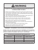
WARNING FAILURE TO FOLLOW SAFE OPERATING PRACTICES MAY RESULT IN SERIOUS INJURY OR DEATH. • Read this manual completely as well as other manuals that came with your mower. • DO NOT operate on steep slopes. To check a slope, attempt to back up it (with the cutter deck down). If the machine can back up the slope without the wheels slipping, reduce speed and use extreme caution. • Under no circumstances should the machine be operated on slopes greater than 15 degrees.
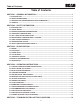
Table of Contents R Table of Contents SECTION 1 - GENERAL INFORMATION. ..................................................................................1 1.1 Introduction............................................................................................................................................1 1.2 Direction Reference............................................................................................................................1 1.
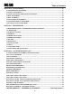
Table of Contents R SECTION 6 - ADJUSTMENTS..................................................................................................22 6.1 PARKING BRAKE ADJUSTMENT.............................................................................................................22 6.2 TRAVEL ADJUSTMENTS...........................................................................................................................22 6.3 Throttle Control and Choke Adjustments....................................
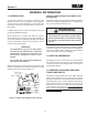
Section 1 R GENERAL INFORMATION 1.1 Introduction USE ONLY SCAG APPROVED ATTACHMENTS AND ACCESSORIES. Your mower was built to the highest standards in the industry. However, the prolonged life and maximum efficiency of your mower depends on you following the operating, maintenance and adjustment instructions in this manual. Attachments and accessories manufactured by companies other than Scag Power Equipment are not approved for use on this machine. See Section 8-1.
Section 1 R 1.
Section 2 R SAFETY INFORMATION 2.1 INTRODUCTION DANGER Your mower is only as safe as the operator. Carelessness or operator error may result in serious bodily injury or death. Hazard control and accident prevention are dependent upon the awareness, concern, prudence, and proper training of the personnel involved in the operation, transport, maintenance and storage of the equipment. Make sure every operator is properly trained and thoroughly familiar with all of the controls before operating the mower.
Section 2 R 3. DO NOT allow children to ride or play on the machine, it is not a toy. 10. Be sure the interlock switches are functioning correctly. 4. Clear the area to be mowed of objects that could be picked up and thrown by the cutter blades. 11. Fuel is flammable; handle it with care. Fill the fuel tank outdoors. Never fill it indoors. Use a funnel or spout to prevent spillage. Clean up any spillage before starting the engine. 5. DO NOT carry passengers. 6.
Section 2 R 2. Reduce speed and exercise extreme caution on slopes and in sharp turns to prevent tipping or loss of control. Be especially cautious when changing directions on slopes. 14. Take all possible precautions when leaving the machine unattended, such as disengaging the mower, lowering the attachments, setting the parking brake, stopping the engine, and removing the key. 3. Stay two cut widths away from slopes, drop offs, ditches and retaining walls. 15.
Section 2 R Lower the roll bar only when absolutely necessary. 22. Use care when approaching blind corners, shrubs, trees, or other objects that may obscure vision. 23. NEVER leave the machine running unattended. 1. To lower the roll bar, remove the hairpin cotter pins and remove the two (2) lock pins. See Figure 2-2. 2.5 ROLL-OVER PROTECTION SYSTEM 2. Lower the roll bar to the down position. 3. To raise the roll bar, lift the bar to the upright position. WARNING 4.
Section 2 R WARNING Failure to properly inspect and maintain the seat belt can cause serious injury or loss of life. 20 o 15 o 10 o 5o 1. Check the full length of the seat belt webbing for cuts, wear, fraying, dirt and stiffness. See Figure 2-3. Figure 2-4. Slope Angle Graph 2. Check the seat belt webbing in areas exposed to ultra violet rays from the sun or extreme dust or dirt.
Section 2 R 2.6 MAINTENANCE CONSIDERATIONS & STORAGE WARNING 1. Never make adjustments to the machine with the engine running unless specifically instructed to do so. If the engine is running, keep hands, feet, and clothing away from moving parts. Hydraulic fluid is under high pressure and can penetrate skin causing injury. If hydraulic fluid is injected into the skin, it must be surgically removed within a few hours by a doctor or gangrene may result. 2.
Section 2 R 2.9 SAFETY AND INSTRUCTIONAL DECALS WARNING INSTALL BELT COVER BEFORE OPERATING MACHINE READ OPERATOR'S MANUAL 483402 FORWARD 483407 F R REVERSE 481568 WARNING 483406 Operation of this equipment may create sparks that can start fires around dry vegetation. A spark arrestor may be required. The operator should contact local fire agencies for laws or regulations relating to fire prevention requirements. 483900 ! Avoid injury from burns. Shut off engine before removing fuel tank cap.
Section 3 R SPECIFICATIONS 3.1 Engine General Type.................................................................................................Heavy Duty Industrial/Commercial Gasoline Brand.......................................................................................................................................................Kawasaki, Kohler Horsepower: Scag Model STWC48V-25CV.......................................................................................
Section 3 R Fuel Tanks........................Dual (4 Gal. RH, 3 Gal. LH) Seamless Polyethylene Tanks with Large Opening and Fuel Cap Seat............................................................................................................................................Padded Suspension Seat Travel Speed: Forward................................................................................................................................................ 0 up to 10 MPH Reverse.....................
Section 4 R OPERATING INSTRUCTIONS 2. Mower Deck Switch (Figure 4-1). Used to engage and disengage the mower drive system. Pulling up on the switch will engage the deck drive. Pushing down on the switch will disengage the deck drive. CAUTION Do not attempt to operate this mower unless you have read this manual. Learn the location and purpose of all controls and instruments before you operate this mower. 3. Engine Choke Control (Figure 4-1). Used to start a cold engine. 4.
Section 4 R 6. Fuse Holders (Figure 4-1). Two 20-amp fuses protect the mower’s electrical system. To replace fuses, pull fuse out of the socket and install a new fuse. 14. Deck Release Lever (Figure 4-1). Used to lock the cutter deck in the transport position. Push the foot pedal forward and pull back on the release lever to release the cutter deck for normal mowing. 7. Left Steering Control (Figure 4-1). Used to control the mower's left wheel when traveling forward or reverse. 15.
Section 4 R 4.4 Starting The Engine Learn to feather the steering controls to obtain a smooth operating action. Practice operating the mower until you are comfortable with the controls before proceeding to mow. CAUTION DO NOT USE STARTING FLUIDS. Use of starting fluids in the air intake system may be potentially explosive or cause a “runaway” engine condition that could result in engine damage and/or personal injury.
Section 4 R 4.6 Engaging The Deck Drive (Cutter Blades) Reverse Travel Caution 1. Set the throttle at about 3/4 speed. Do not attempt to engage the deck drive at high speed as this shortens the electric clutch life — use only moderate engine speed when engaging the deck drive. Disengage power to the mower before backing up. Do not mow in reverse unless absolutely necessary and then only after observation of the entire area behind the mower. 2.
Section 4 R 4.7 Hillside Operation 5. Engage the parking brake. 6. Turn the ignition key to the OFF position and remove the key. WARNING 4.9 After Operation DO NOT operate on steep slopes. To check a slope, attempt to back up it (with the cutter deck down). If the machine can back up the slope without the wheels slipping, reduce speed and use extreme caution. Under no circumstances should the machine be operated on slopes greater than 15 degrees.
Section 4 R 1. If the discharge chute becomes clogged, shut off the engine and remove the ignition key. Using a stick or similar item, dislodge the clogged material. Then resume normal mowing. 3. Cut grass when it is dry and not too tall. Do not cut grass too short (cut off 1/3 or less of existing grass for best appearance). Mow frequently. 4.11 Moving Mower With Engine Stopped 5. When mowing wet or tall grass, mow the grass twice.
Section 4 R 3. If adjustment of the steering levers is needed, use the following instructions to adjust. 43 15 48 3 2 A. Loosen the tension knob on the lever assembly. 5 G IN TT HT CU EIG H 4 1/4 1/2 3/4 2 1 1/4 HEIGHT ADJUSTMENT PEDAL B. Rotate the steering lever forward or backward to achieve the optimum operating position. LANYARD PIN C. Tighten the tension knob and repeat on the opposite side. D.
Section 5 R TROUBLESHOOTING CUTTING CONDITIONS Condition Cause Stringers - Occasional Low engine RPM Blades of Uncut Grass Width of Deck SGB020 Cure Run engine at full RPM Ground speed too fast Slow speed to adjust for conditions Wet grass Cut grass after it has dried out Dull blades, incorrect sharpening Sharpen blades Deck plugged, grass accumulation Clean underside of deck Belts slipping Adjust belt tension Streaking - Strips of Dull, worn blades Uncut Grass in Cutting Path Incorrect bla
Section 5 R TROUBLESHOOTING CUTTING CONDITIONS (CONT'D) Condition Cause U ne v en C ut on F lat Lift worn from blade Ground - Wavy High-Low Appearance, Scalloped Blade upside down Cut, or Rough Contour Cure Replace blade Mount with cutting edge toward ground Deck plugged, grass accumulation Clean underside of deck Too much blade angle (deck pitch) Adjust pitch and level Deck mounted improperly See your authorized SCAG dealer Bent spindle area See your authorized SCAG dealer Dull blade Sharpen
Section 5 R TROUBLESHOOTING CUTTING CONDITIONS (CONT'D) Condition Cause Scalping - Blades Hitting Low tire pressures Dirt or Cutting Very Close to the Ground Ground speed too fast Width of Deck Cure Check and adjust pressures Slow speed to adjust for conditions Cutting too low May need to reduce ground speed, raise cutting height, change direction of cut, and/or change pitch and level Rough terrain May need to reduce ground speed, raise cutting height, and/or change direction of cut Ground speed
Section 6 R ADJUSTMENTS 6.1 PARKING BRAKE ADJUSTMENT STC2002BA WARNING Do not operate the mower if the parking brake is not operable. Possible severe injury could result. LOOSEN HERE The parking brake linkage should be adjusted whenever the parking brake lever is placed in the “ENGAGE” position and the parking brake will allow the mower to move. If the following procedures do not allow you to engage the parking brake properly, contact your Scag dealer for further brake adjustments.
Section 6 R Neutral Adjustment Tracking Adjustment 1. Be sure the dump valve levers are in the run position and the steering control levers are in the neutral lock position. Caution 2. With an operator in the seat, start the engine and disengage the parking brake. Stop the engine and remove the key from the ignition before making any adjustments. Wait for all moving parts to come to a complete stop before beginning work. 3.
Section 6 R 6.6 CUTTER DECK ADJUSTMENTS A. Stop the machine and place the steering control levers in the neutral position. Loosen the lock nuts securing the ball joints at each end of the RH steering control rod. Rotate the control rod to lengthen the rod and tighten the lock nuts. This will cause the control rod to stroke the RH pump less, slowing down the RH wheel. See Figure 6-3. Cutter deck level, pitch and height are set at the factory.
Section 6 R Cutter Deck Pitch Cutter Deck Height The pitch of the cutter deck should be equal between the front and rear of the cutter deck for proper cutting performance. To check for proper deck pitch, be sure that the mower is on a flat, level surface and the tires are properly inflated. The cutter deck height adjustment is made to ensure that the cutter deck is cutting at the height indicated on the cutting height index gauge.
Section 6 R 3. Check the cutter deck cutting height by placing the lanyard pin in the 3" position on the cutting height index. Release the deck from the transport position and allow the deck to move to the 3" cutting height position. B. 4" (factory setting), 4-1/4" or 4-1/2" Position - (See Figure 6-9). For general purpose cutting. This gives the best mix of cutting performance in all types of grass. C. 4-3/4" or 5-1/4" Position - (See Figure 6-9).
Section 6 R 6.8 electric clutch adjustment ADJUSTMENT NUTS The electric clutch serves two functions in the operation of the mower. In addition to starting and stopping the power flow to the cutter blades, the clutch also acts as a brake to assist in stopping blade rotation when the PTO is switched off or the operator presence circuit is interrupted. When the clutch is disengaged, the air gap between the armature and rotor must be adjusted to fifteen thousandths of an inch, 0.015, for proper operation.
Section 7 R MAINTENANCE 7.1 Maintenance Chart - Recommended Service Intervals HOURS Break-In (First 10) 8 20 40 100 200 Procedure 500 Comments X Check all hardware for tightness X Check hydraulic oil level X C h e c k a l l b e l t s f o r p r o p e r See paragraph 7.8 alignment X Change engine oil and filter See paragraph 7.4 X Check coolant level See paragraph 7.11 See paragraph 7.
Section 7 R MAINTENANCE CHART - RECOMMENDED SERVICE INTERVALS (CONT'D) HOURS Break-In (First 10) 8 40 100 200 Procedure 500 Comments X Apply grease to fittings See paragraph 7.2 X Check hardware for tightness X Change engine oil filter See paragraph 7.4 X Check hydraulic oil level See paragraph 7.3 X Replace engine fuel filter See paragraph 7.5 X Drain hydraulic system and Use SAE 20W50 Motor Oil. replace hydraulic oil See paragraph 7.
Section 7 R GREASE FITTING LUBRICATION Lubricant Interval Lithium MP White Grease 2125 (40 Hours/Weekly) Chassis Grease (100 Hours/Bi-monthly) Chassis Grease (200 Hours/Monthly) 6 Chassis Grease (500 Hours/Yearly) 4 3 5 7 2 6 8 1 2 4 5 3 Figure 7-1.
Section 7 R 7.3 Hydraulic System - IMPORTANT The hydraulic oil should be changed if you notice the presence of water or a rancid odor to the hydraulic oil. A. Checking Hydraulic Oil Level The hydraulic oil level should be checked after the first 10 hours of operation. Thereafter, check the oil after every 200 hours of machine operation or monthly, whichever occurs first. 1. Park the mower on a level surface and stop the engine. 2. Place a suitable container under the hydraulic oil filter.
Section 7 R C. Changing Engine Oil Filter C. Changing Hydraulic Oil Filter Element After the first 20 hours of operation, replace the engine oil filter. Thereafter, replace the oil filter after every 200 hours of operation or every month, whichever occurs first. Refer to Engine Operator’s Manual for instructions. See Figure 7-4. The hydraulic oil filter should be changed after every 500 hours of operation or annually, whichever occurs first. 1. Remove the oil filter element and properly discard it.
Section 7 R 7.6 Engine Air Cleaner To avoid personal injury or proper ty damage, use extreme care in handling gasoline. Gasoline is extremely flammable and the vapors are explosive. A. Cleaning and/or Replacing Air Cleaner Element 1. Extinguish all cigarettes, cigars, pipes and other sources of ignition. For any air cleaner, the operating environment dictates the air cleaner service periods.
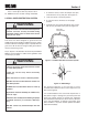
Section 7 R WARNING WARNING BATTERIES PRODUCE EXPLOSIVE GASES. Charge the battery in a well ventilated space so gases produced while charging can dissipate. Electric storage battery fluid contains sulfuric acid which is POISON and can cause SEVERE CHEMICAL BURNS. Avoid contact of fluid with eyes, skin, or clothing. Use proper protective gear when handling batteries. DO NOT tip any battery beyond 45° angle in any direction. If fluid contact does occur, follow first aid suggestions below.
Section 7 R 7.9 Cutter Blades Angle Blade Back Do Not Cut In A. Blade Inspection 1. Remove the ignition key before servicing the blades. X 2. Raise the mower deck to the highest position. Place the lanyard pin in the highest cutting height position to prevent the cutter deck from falling. X Must NOT Exceed 1/3 Blade Width 30 SGB033 Figure 7-6. Blade Sharpening WARNING 2. Check the balance of the blade. If the blades are out of balance, vibration and premature wear can occur.
Section 7 R 7.11 Cooling System HEX NUT-TORQUE TO 75 LB-FT (Liquid-Cooled Machines Only) WARNING SPINDLE SHAFT CUTTER DECK To avoid burns, always allow the engine to cool before removing the radiator cap. A. Checking Coolant Level HEX HEAD BOLT / NUT The coolant level should be checked before each day of operation. SPINDLE ASSEMBLY CUTTER BLADE SPACER 1. Remove the radiator cap by turning it slowly counterclockwise to the first stop and allow any pressure to be released.
Section 7 R - NOTE - 7.12 Body, Deck, And Upholstery The cooling system should be flushed and the coolant replaced every 500 hours of operation or annually. See your Scag dealer for proper coolant replacement. Caution Do not wash any portion of the equipment while it is hot. Do not wash the engine; use compressed air. B. Cleaning the Radiator Debris Screen After each day of operation, remove and clean the radiator debris screen. Caution 1. After each use, wash the mower and cutter deck.
Section 7 R NOTES 38
Section 8 R ILLUSTRATED PARTS LIST 8.1 Scag Approved Attachments And Accessories Attachments and accessories manufactured by companies other than Scag Power Equipment are not approved for use on this machine.
Section 8 R 48V & 52V CUTTER DECKS 14 55 55 52, 52A 14 29 80 53 53 65 55 18 56 72 4 48 73 29 21 49 67 13 3 31 51 53 74 49 11 64 60 62 61 14 49 84 54 81 83 13 15 50 66 28 49 83 13 23 20 87 83 17 3 2 70 26 30 3 32 3 12 * 59 58 66 63 56 29 21 3 82 3 75 76 33 77 6 7 8 70 26 84 35 36 24 10 5 25 78 79 88 86 37 13 66 89 1 27 38 85 57 40 19 41 22 68 42 69 34 46 47 29 37 9 43 16 44 45 71 STC 2006 CD4852 Rev.
Section 8 R 48V & 52V CUTTER DECKS Ref. No. 1 2 3 4 5 6 7 8 9 10 11 12 13 14 15 16 17 18 19 20 21 22 23 24 25 26 27 28 29 30 31 32 33 34 35 36 37 38 39 40 41 42 43 44 45 46 47 48 49 50 Part No.
Section 8 R 61V CUTTER DECK 24 14 53 52 32 72 18 51 29 21 56 4 65 93 49 11 67 50 79 31 "A" 56 55 13 64 60 62 61 54 59 58 66 63 53 94 13 91 29 79 15 32 56 21 66 30 23 78 13 92 20 56 82 "A" 2 80 12 2 80 6 7 8 3 87 88 80 76 78 88 80 81 28 80 75 77 80 13 33 26 35 80 71 36 89 10 90 13 5 25 66 27 17 81 84 83 85 74 73 37 12 86 1 40 19 57 41 22, 22A 68 42 69 34 46 70 29 38 47 37 9 43 16 44 45 STWC 2006 CD61 42
Section 8 R 61V CUTTER DECK Ref. No. 1 2 3 4 5 6 7 8 9 10 11 12 13 14 15 16 17 18 19 20 21 22 23 24 25 26 27 28 29 30 31 32 33 34 35 36 37 38 39 40 41 42 43 44 45 46 47 48 49 50 Part No.
Section 8 R CUTTER DECK CONTROLS 5 4 3 38 12 2 18 46 20 21 26 33 27 17 1 6 41 13 7 42 45 14 46 15 37 36 16 11 9 30 8 10 22 32 24 40 43 34 44 24 28 35 29 25 19 24 23 24 25 19 29 23 24 25 28 31 CUTTER DECK 44 STC 2006 CDC
Section 8 R CUTTER DECK CONTROLS Ref. No. 1 2 3 4 5 6 7 8 9 10 11 12 13 14 15 16 17 18 19 20 21 22 23 24 25 26 27 28 29 30 31 32 33 34 35 36 37 38 39 40 41 42 43 44 45 46 Part No.
Section 8 R SHEET METAL COMPONENTS 26hp Kawasaki 25 24 23 6 3 5 29 61 22 21 2 53 18 19 47 57 15 58 59 11 60 7 8 20 54 16 10 9 55 4 19 26 17 13 15 28 19 4 14 56 15 46 12 27 12 47 12 16 21 15 31 32 33 35 30 52 51 1 50 33 34 42 30 36 44 43 45 37 40 38 39 49 44 41 46 42 STWC 2011 SMC
Section 8 R SHEET METAL COMPONENTS Ref. No. 1 2 3 4 5 6 7 8 9 10 11 12 13 14 15 16 17 18 19 20 21 22 23 24 25 26 27 28 29 30 31 32 33 34 35 36 37 38 39 40 41 42 43 44 45 Part No.
Section 8 R STWC ROLL-OVER PROTECTION SYSTEM 1 2 3 5 2 4 6 7 2 3 2 6 3 7 4 1 1 10 9 8 10 9 8 2011 STC ROPS 48 5 2
Section 8 R STWC ROLL-OVER PROTECTION SYSTEM Ref. No. 1 2 3 4 5 6 7 8 9 10 Part No. 462209 484168 484170 484169 04001-90 04021-19 484167 04021-19 04040-13 04001-145 Description STC Foldable ROPS Pin Assembly (incl. #3 & #4) Spring, ROPS Clip, ROPS Bolt, Hex Head 1/2-13 x 3-1/4" Nut, Center Lock 1/2-13 Spring Clip, ROPS Nut, Center Lock 1/2-13 Flatwasher, 1/2-.562 x 1.375 x .
Section 8 R STWC SUSPENSION SEAT 2 3 4 6 5 11 7 4 1 3 2 10 8 14 13 12 13 12 13 12 13 9 12 Ref. No. 1 2 3 4 5 Part No. 11 9292 04001-178 04040-11 483594 482950 482945 482946 482940 482943 482948 482942 482952 482944 482948 482941 12 13 14 04001-12 43572 483440 6 7 8 9 10 Description Suspension Seat Assembly w/seat belt Bolt, Hex Head 7/16-20 x 1” Flatwasher, 7/16-.500 x 1.25 x .
Section 8 R NOTES 51
Section 8 R DRIVE SYSTEM COMPONENTS 5 21 22 24 26 25 21 20 1 18 27 17 2 10 2 15 6 3 28 30 28 14 23 27 1 1 4 19 29 7 11 8 9 7 11 12 16 10 13 10 1 12 16 STWC 2008 DSC 52
Section 8 R DRIVE SYSTEM COMPONENTS Ref. No. 1 2 3 4 5 6 7 8 9 10 11 12 13 14 15 16 17 18 19 20 21 22 23 24 25 26 27 28 29 30 Part No. 04021-09 04019-04 483087 43286 04001-22 461603 04063-14 483172 483415 04043-04 482744 482085 04001-45 43503 48224 04001-172 04001-31 04001-20 483081 421203 04017-05 422969 04001-19 04030-02 48829 04060-06 04001-136 04019-04 483215 424137 Description Nut, Elastic Stop 3/8-16 Nut, Serr. Flng. 3/8-16 Spring, Pump Idler Spacer Bolt, Hex Hd. 3/8-16 x 2-3/4” Idler Arm Assy.
Section 8 R ENGINE AND ATTACHING PARTS 17 7 1 14 2 5 4 3 4 12 8 15 16 11 6 9 13 4 10 4 2011 STWC EAP 54
Section 8 R ENGINE AND ATTACHING PARTS Ref. No. 1 2 3 4 5 6 7 8 9 10 11 12 13 14 15 16 17 Part No.
Section 8 R STEERING COMPONENTS 1 2 3 4 8 5 44 38 18 18 39 41 40 6 7 21 42 45 8 30 25 20 32 19 17 34 37 35 34 27 26 15 17 28 4 5 24 33, 33A 35 31 9 29, 29A 23 22 To Pump 14 16 13 12 11 10 STC 2006 SSC REV 1 56
Section 8 R STEERING COMPONENTS Ref. No. 1 2 3 4 5 6 7 8 9 10 11 12 13 14 15 16 17 18 19 20 21 22 23 24 25 26 27 28 29 30 31 32 33 34 35 36 37 38 39 40 41 42 43 44 45 Part No.
Section 8 R BRAKE COMPONENTS 4 5 18 7 6 8 9 44 36 10 38 26 34 33 30 25 24 21 6 20 22 23 20 19 35 24 32 20 40 16 17 35 43 27 41 24 2 26 28 42 1 31 11 3 15 14 13 12 STC 2002 BSC 58
Section 8 R BRAKE COMPONENTS Ref. No. 1 2 3 4 5 6 7 8 9 10 11 12 13 14 15 16 17 18 19 20 21 22 23 24 25 26 27 28 29 30 31 32 33 34 35 36 37 38 39 40 41 42 43 44 Part No.
Section 8 R HYDRAULIC SYSTEM 48 A 45 8 B 4 G 2 9 N 1 F 12 7 36 14 15 F 12 10 7 36 1 4 A E 1 4 B 9 23 24 39 K 3 45 D 13 17 16 21 22 30 28 46 35 29 5 20 19 N 6 31 44 59 C G 27 8 4 12 11 9 11 C D 9 25 18 19 J 20 3 20 19 18 K 4 32 J 36 37 E 44 31 42 58 37 26 4 36 41 26 38 26 43 34 47 40 STWC 2011 HS 60
Section 8 R HYDRAULIC SYSTEM Ref. No. 1 2 3 4 5 6 7 8 9 10 11 12 13 14 15 16 17 18 19 20 21 22 23 24 25 26 27 28 29 30 31 32 33 34 35 Part No.
Section 8 R STWC FUEL SYSTEM - EPA PHASE 2 (models produced prior to 1/1/2011) 1 2 3 4 5 4 9 M 6 4 5 5 7 8 10 M 9 TO ENGINE 13 9 L 11 9 12 8 L 7 STC 2011 FS EPA PHASE 2 62
Section 8 R STWC FUEL SYSTEM - EPA PHASE 2 (models produced prior to 1/1/2011) Ref. No. Part No. 1 2 3 4 5 6 7 8 9 10 11 12 13 483792 482774 462163 04030-03 04001-08 04040-15 482571 483748 483617 423912 482212 * 462162 Description Fuel Cap Gasket, Fuel Cap Fuel Tank RH (incl. #7 & #8) Lockwasher, 5/16" Spring Bolt, Hex Head 5/16-18 x 3/4" Flatwasher, 5/16-.375 x .875 x .083 Tank Bushing Fitting, 90 Degree Fuel Hose, 1/4" I.D.
Section 8 R STWC FUEL SYSTEM - EPA PHASE 3 (models produced after 1/1/2011) 10 To Fuel Pump 9 M To Engine Purge Port 21 15 1 L 11 B 9 24 12 14 19 22 20 2 25 Tank 22 23 21 3 15 18 15 21 21 4 5 M 6 4 25 20 22 13 5 7 23 19 22 9 Purge 15 21 21 15 4 A B 17 A 5 15 16 8 9 8 L 7 STC 2011 FS CARB TEIR 3 64
Section 8 R STWC FUEL SYSTEM - EPA PHASE 3 (models produced after 1/1/2011) Ref. No. Part No. 1 2 3 4 5 6 7 8 9 10 11 12 13 14 15 16 17 18 19 20 21 22 23 24 25 484286 484279-01 462298 04030-03 04001-08 04040-15 482571 483748 483617 423912 482212 * 462297 484342 484347 48136-17 452176 48935-02 484284 484285 48059-05 48059-02 484343-01 425559 484347 Description Fuel Cap w/ Tethered Tube, Fuel Tank Insert Fuel Tank RH (incl.
Section 8 R ELECTRICAL SYSTEM - KOHLER & KAWASAKI AIR-COOLED 1 27 29 23 38 25 30 39 40 6 20 41 26 31 32 12 33 21 14 34 10 17 11 16 15 18 19 10 11 24 7 35 8 36 12 37 5 9 10 11 42 2 45 43 66 13 3 20 44 4 20 12 2 42 P S O W E C R E Q A G U IP M E N T STC 2011 ESKA
Section 8 R ELECTRICAL SYSTEM - KOHLER & KAWASAKI AIR-COOLED Ref. No. 1 2 3 4 5 6 7 8 9 10 11 12 13 14 15 16 17 18 19 20 21 22 23 24 25 26 27 28 29 30 31 32 33 34 35 36 37 38 39 40 41 42 43 44 45 Part No.
Section 8 R ELECTRICAL SYSTEM - 26HP KAWASAKI LIQUID-COOLED 1 42 27 29 23 38 25 30 39 40 6 20 15 26 31 32 17 12 14 34 33 21 10 18 11 16 41 14 10 19 11 24 7 35 8 36 12 37 5 45 2 43 68 4 13 3 20 44 46 20 9 10 11 12 2 42 P S O W E C R E Q A G U IP M E N T STWC 2008 ESKALC
Section 8 R ELECTRICAL SYSTEM 26HP KAWASAKI LIQUID-COOLED Ref. No. 1 2 3 4 5 6 7 8 9 10 11 12 13 14 15 16 17 18 19 20 21 22 23 24 25 26 27 28 29 30 31 32 33 34 35 36 37 38 39 40 41 42 43 44 45 46 Part No.
Section 8 R HYDRAULIC PUMP ASSEMBLY 29 l ea S ul a rh ve Kit 20 21 23 22 1718 O 15 14 13 16 30 12 11 19 25 PORT "A" SIDE 24 3 1 27 26 5 4 6 7 2 8 24 28 10 PORT "B" SIDE 9 70 30
Section 8 R HYDRAULIC PUMP ASSEMBLY Ref. No. 1 2 3 4 5 6 7 8 9 10 11 12 13 14 15 16 17 18 19 20 21 22 23 24 25 26 27 28 29 30 Part No. HG 70516 HG 70573 HG 50641 HG 50969 HG 51232 HG 2513027 HG 50273 HG 9004101-1340 HG 50095 HG 2513030 HG 70521 HG 50315 HG 51161 HG 50329 HG 50951 HG 70331 HG 2003014 HG 2003017 HG 51444 HG 2003087 HG 50551 HG 2003005 HG 2000015 HG 2510062 HG 70403 HG 2513043 HG 9005110-4400 HG 50408 HG 70525 HG 70743 Description Housing Kit End Cap Kit Straight Headless Pin Hex Flng.
Section 8 R REPLACEMENT DECALS AND INFORMATION PLATES 1 ISO 9001 Registered 2 8 48404 __________ __________ __________ __________ __________ __________ __________ __________ __________ __________ __________ __________ __________ __________ __________ __________ 11 FORWARD F 5 R REvERSE 482100 6 Heavy-Duty Commercial 481971 13 7 WARNING INSTALL BELT COvER BEFORE OPERATING MACHINE READ OPERATOR'S MANUAL 4 483402 9 10 19 12 18 STWC 2011 RDP1 72
Section 8 R REPLACEMENT DECALS AND INFORMATION PLATES Ref. No. 1 2 3 4 5 6 7 8 9 10 11 12 13 14 15 16 17 18 19 ** ** Part No.
Section 8 R ELECTRICAL SCHEMATIC - KOHLER AIR-COOLED PTO SWITCH DIODE KEY SWITCH RELAY GRN W/BLK STRIPE GREEN GRN W/WHT STRIPE YELLOW RED W/YEL STRIPE RED RED WHITE GREEN RED BLACK RED W/YEL STRIPE RED BLUE RED LIGHT BLUE 20 AMP FUSES KOHLER ADAPTER HARNESS RED W/YEL STRIPE BRAKE INTERLOCK SWITCH ENGINE PLUG WHITE YELLOW WHITE YELLOW RED GRN W/BLK STRIPE RED RED BLACK BLUE LIGHT BLUE SOLENOID "B+" RED GRN W/WHT STRIPE GRN W/WHT STRIPE MAIN HARNESS RED PINK RED L.H.
Section 8 R ELECTRICAL SCHEMATIC - KAWASAKI AIR-COOLED PTO SWITCH RELAY KEY SWITCH GREEN GRN W/BLK STRIPE GRN W/WHT STRIPE RED W/YEL STRIPE YELLOW RED RED WHITE GREEN BLACK RED RED W/YEL STRIPE RED BLUE LIGHT BLUE RED 20 AMP FUSES YELLOW WHITE RED GRN W/BLK STRIPE BLACK RED RED BLUE BLACK LIGHT BLUE GRN W/WHT STRIPE BRAKE INTERLOCK SWITCH PINK RED RED RED PINK RED L.H.
Section 8 R ELECTRICAL SCHEMATIC - 26HP KAWASAKI LIQUID-COOLED WATER TEMP GAUGE PTO SWITCH KEY SWITCH RELAY GRN W/WHT STRIPE GRN W/BLK STRIPE RED W/YEL STRIPE YELLOW RED RED RED GREEN WHITE YELLOW GRN W/WHT STRIPE RED BLACK RED BLACK BLUE LIGHT BLUE WHITE W/BLACK STRIPE BLACK RED RED BLACK RED RED RED BLUE RED LIGHT BLUE 20 AMP FUSES BRAKE INTERLOCK SWITCH L.H.
LIMITED WARRANTY - COMMERCIAL EQUIPMENT Any part of the Scag commercial mower manufactured by Scag Power Equipment and found, in the reasonable judgment of Scag, to be defective in materials or workmanship, will be repaired or replaced by an Authorized Scag Service Dealer without charge for parts and labor during the periods specified below. This warranty is limited to the original purchaser and is not transferable. Proof of purchase will be required by the dealer to substantiate any warranty claims.
© 2011 Scag Power Equipment Division of Metalcraft of Mayville, Inc.