A S S E M B LY- A N D I N S T R U C T I O N S M A N U A L Scan 58 - series Congratulations on your new Scan wood-burning stove You have purchased a product by one of Europe’s leading manufacturer’s of wood-burning stoves, and we are sure that you will have years of pleasure with your purchase. To make the best possible use of your stove, it is important that you follow our advice and instructions. Please read this Assembly- and instructions manual before you start to assemble your stove.
CONTENTS 2 Table of contents Technical data .............................................................................................. 3 Installation Safety Technical data and dimensions Dimension sketch for Scan 58 - series Type plate Assembly ......................................................................................................
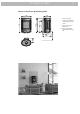
T E C H N I C A L D ATA 3 Installation Technical data and dimensions The house owner is responsible for ensuring that all necessary national and local safety measures are observed during installation and fitting and also responsible for observing the fitting and operating instructions detailed in this manual. Materials: When you install any kind of fireplace or stove, you must inform the local authorities.
T E C H N I C A L D ATA 4 Dimension sketch Scan 58 with "see through" plinth * Height to the beginning of the connecting piece at top outlet ** Centre of fresh air intake bottom *** Centre of fresh air intake rear * Centre rear outlet ** Height to the beginning of the connecting piece at top outlet *** Centre of fresh air intake bottom 998* 1112** 350 1138 500 Ø108 175 175*** Dimension sketch Scan 58 with pedestal plinth 998* **** Centre of fresh air intake rear 294**** 1112** 35
T E C H N I C A L D ATA 5 Dimension sketch Scan 58 Wall-hung model 764 624* 572* 350 736** 684** 500 * Centre rear outlet ** Height to the beginning of the flue pipe at top outlet *** Centre of fresh air intake bottom 184*** 228 403 430**** **** Minimum clearance above flammable mate rial
T E C H N I C A L D ATA 6 Dimension sketch Scan 58-7 and Scan 58-8 1140 1114** 350 1000* 500 * Centre rear outlet ** Height to the beginning of the connecting piece at top outlet *** Centre of fresh air intake bottom 296**** **** Centre of fresh air intake rear Ø114 175 131*** Dimension sketch Scan 58-7 and Scan 58-8 with high top 350 296*** 1000* 1114** 1572 500 Ø114 175 131*** * Height to the beginning of the connecting piece at top outlet ** Centre of fresh air intake botto
T E C H N I C A L D ATA 7 Dimension sketch Scan 58-9 and Scan 58-10 1114** 1000* 350 1140 586 * Centre rear outlet ** Height to the beginning of the connecting piece at top outlet *** Centre of fresh air intake bottom 296**** **** Centre of fresh air intake rear Ø114 175 131*** Dimension sketch Scan 58-9 and Scan 58-10 with high top 350 296*** 1114* 1000 1572 586 Ø114 175 131** * Height to the beginning of the connecting piece at top outlet ** Centre of fresh air intake bottom
T E C H N I C A L D ATA 8 Type plates All Scan wood-burning stoves are fitted with a type plate, that specifies the approval standards and the distance to flammable materials. The type plate on the Scan 58-7, Scan 58-8, Scan 58-9 and Scan 58-10 is located in the magazine under the combustion chamber.
T E C H N I C A L D ATA Scan 58-2 Wall & Scan 58-5 Wall (with half lateral glass panes) 9 Scan 58-7 & Scan 58-8 Scan 58-2 Wall + Scan 58-5 Wall Scan 58-7 + Scan 58-8 Wall mounted room heater fired by solid fuel Freestanding room heater fired by solid fuel Standard: EN 13240 EC no. 90358612 Standard: EN 13240 EC no.
A S S E M B LY 10 Scan 58-9 & Scan 58-10 Transport brackets For Scan 58 with pedestal and see-through base / Scan 58 wall model, remove the transport brackets as shown below. Scan 58-9 + Scan 58-10 Freestanding room heater fired by solid fuel Standard: EN 13240 EC no.
A S S E M B LY 11 Positioning your wood-burning stove The wood-burning stove must be set up so that the stove itself, the flue pipe, and the chimney can all be cleaned. Position near to non-flammable walls When positioning near a non-flammable wall, we recommend you keep a minimum distance of 50 mm between the rear of the product and the wall for cleaning purposes. Distance to furniture: 1000 mm But please check to avoid furniture or other furnishings being dried out due to being too close to the stove.
A S S E M B LY 12 Scan 58-1 Wall & Scan 58-4 Wall (without lateral glass panes) Non-flammable wall Adjusting screws The Scan 58 has four adjusting screws under the plinth of the woodburning stove. Use the adjusting screws to get the stove to stand vertically. Flammable wall Tilt the plinth and adjust the screws before fitting the stove in place. On the Scan 58-7, Scan 58-8, Scan 58-9 and Scan 58-10 you can also choose to adjust the adjustment screws in the magazine under the combustion chamber.
A S S E M B LY Load bearing underlay All of the products in our portfolio are classified as light-duty fireplaces; in most cases, there is no need to reinforce the floor, so that you can typically use the normal floor. However, you should make sure that the load bearing underlay can bear the weight of the wood-burning stove and that of the chimney.
A S S E M B LY 14 Fitting the stove onto the plinth Fresh air intake There are two plinths for the Scan 58. You can see how to fit these below. Use the key supplied with the service pack to make the attachment secure. In a well-insulated house, the air used up by the burning process has to be replaced. This particularly applies to houses with mechanical ventilation. There are different ways of making sure that an air exchange takes place.
A S S E M B LY 15 The Scan 58 with "see through" plinth Connecting piece top outlet External combustion air can be connected underneath the combustion chamber using the connection piece supplied and connecting outdoor air. Your wood-burning stove has been prepared for a top outlet by the manufacturer. Remove the cover plate from the top plate, and fit the connecting piece, the enclosed seal, and the fittings from the service package.
A S S E M B LY 16 Preparing the stove for rear outlet Remove the top plate and the frame for the top plate. The Allen screws and discs are to be reused, when the stove is assembled again. Loosen the cast iron cooking plate from the inside and remove. This is to be used later as a seal and cover at the top of the smoke outlet. C Fit the separate connecting piece in place from the outside and fix in place using the bracket and seal supplied in the service pack. Fit the frame for the top plate.
A S S E M B LY Fit the cast iron cooking plate in the smoke outlet. Place the top plate on the stove. 17 Wall-hung model Installation must be planned and executed in accordance with national and local building regulations. The stove must only be fitted to a non-flammable wall. There must be no form of flammable component in the wall. In the case of thin walls, nor must there be any behind the wall. The load-bearing capacity of the wall must be checked under all circumstances.
A S S E M B LY 18 Fit the wall brackets to the wall. Fit the washers and screws for the rear casing (E). Fasten these only once fitting of the stove is complete. Hang the stove on the wall bracket. The pegs in the wall bracket must ‘catch’ in the holes at the bottom of the stove (F). Fit and tighten the screws for the wall bracket and stove (G). 98,5 Fitting of the stove is now complete. Tighten the screws and washers in the rear casing (E).
A S S E M B LY Scan 58-9 and Scan 58-10 Scan 58-9 and Scan 58-10 are delivered with loose soap stone plates for mounting on the sides of the stove. 19 Each soap stone is to be mounted with distance bushings and screws (pos. H). These are delivered together with the stove. Use a Torx screwdriver for tightening the screws. You are not to use any electrical tools, as this might tighten the screws too much, resulting in the soap stones breaking.
ACC ESSOR I ES 20 Scan 58-9 and Scan 58-10 with high top The high top and the chimney are mounted as described in the section ”Mounting of high top for Scan 58-7 and Scan 58-8 on page 21”. In order to prepare the stove for mounting of soap stones, we refer to the section ”Scan 58-9 and Scan 58-10”, page 19. However, the soap stones must be mounted according to the size as shown below (the smaller stone in the middle).
ACC ESSOR I ES Mounting of high top for Scan 58-7 and Scan 58-8 If you choose to connect the stove with an elbow pipe or a rear outlet, the stove must be mounted to the wall behind the oven using a special wall mounting kit. This kit can be purchased from your local Scan dealer. For fitting, see page 24. 21 Remove the top plate and the frame for the top plate. The Allen screws and discs (pos. L) are to be reused when the high top is fastened on the stove.
ACC ESSOR I ES 22 For mounting of the flue collar, see page 15: “Connecting piece top outlet”. Mount the high top, adjust the height and tighten it. L Screws for height adjustment of the high top Place the top plate and the frame for the top plate on the stove without fastening them. Mount the chimney.
ACC ESSOR I ES Remount the front plate for the high top and tighten it. 23 Fasten the frame for the top plate (the heat shield must turn towards the door) with the screws and discs (pos. M) delivered with the high top. M Screws for adjusting the height of the frame for the top plate Screws for adjusting the height of the top plate Heat shield M 4 x allen screws M6510 4 discs Ø 6.5 / Ø16 x 1.1 Tighten the screws in the bottom of the front plate.
ACC ESSOR I ES 24 Wall mounting kit for Scan 58 with high top Scan 58 high top with elbow pipe If you choose to connect the stove with an elbow pipe or a rear outlet, the stove must be mounted to the wall behind the oven using a special wall mounting kit. This kit can be purchased from your local Scan dealer N: See page 21 for how to fit the high top. Fasten the safety wire and the wire bushing to the wire bushing casing using a pointed screw.
ACC ESSOR I ES 25 O: Fasten the safety wire to the high top with a nipple screw. See page 23 for how to fit the top plate and front plate for the high top.
ACC ESSOR I ES Scan 58 high top with rear outlet If you have chosen to connect a Scan 58 high top with a rear outlet, there are two more fixing holes in the high top for fastening the safety wire. Fixing hole for fastening the safety wire in the high top. Fixing hole for fastening the safety wire in the high top.
ACC ESSOR I ES 27 Heat accumulating stones for high top The heat accumulating stones for Scan 58 with high top are made of a special material with a high heating capacity. The stones are heated up during the firing and gives off the heat again after the firing, which means that the stove stays warm for a longer time. The vent for adjustment of the convection air is placed at the back of the high top, see page 30 for adjustment of the vent. Firing with the vent open will give a quicker heating.
ACC ESSOR I ES 28 Fitting the soapstone top You can buy a soapstone top for the Scan 58 as an accessory. Remove the top plate. Refit the four Allen screws and place the soapstone top in position. Removing the top plate N Fitting the soapstone top N N 4 x Allen screws M6x10 Soap stone top for stove with soap stone sides (Scan 58-9 and Scan 58-10) with and without high top.
ACC ESSOR I ES 29 Fit the brackets and hook the door on (top left corner first). Fitting a storage door You can buy a storage door for the Scan 58 with "see through" plinth as an accessory. Fit this as shown below. Put the bottom plate in position. Magnet for door Fit the rear plate via slots in the stove and holes in the bottom plate.
I NSTRUCTION FOR USE CB Technology (Clean Burning) Baffle plates Your wood-burning stove is fitted with CB technology. To ensure optimum burning of the gases released by the burning process, air is guided by a specially developed system. Pre-heated air is led into the combustion chamber through the small holes below the baffle plates. The airflow is driven by the combustion speed, and cannot be regulated. The baffle plates are located in the upper part of the combustion chamber.
I N S T R U C T I O N S F O R H E AT I N G 31 Environmentally-Friendly Heating Continuous firing Avoid restricting your wood-burning stove to an extent where no flames are visible during the degasifying period, as this leads to particularly inefficient heating. The gases released by the wood do not burn due to the low temperature in the combustion chamber. Part of the gas condenses in the wood-burning stove and flue system as soot, and this could lead to your chimney catching fire.
I N S T R U C T I O N S F O R H E AT I N G General Notes Handling fuels Your wood stove is not designed for continual heating for periods of over 24 hours. Selecting Wood/Fuel Please note! Parts of the wood-burning stove, especially the outer surfaces, become hot during use. Please exercise due care. Never empty ashes into a flammable container. Ashes can contain glowing embers long after you finish using your wood stove.
MAINTENANCE Maintaining your wood-burning stove 1. Lift up the baffle plate, and remove the pin that holds the baffle plate in place. 2. Lower the baffle plate. 3. Turn the baffle plate sideways inside the stove. Apart from regular chimney sweeping, your wood-burning stove does not require any regular maintenance. Coated surfaces Clean your wood-burning stove by dusting with a dry, lint-free cloth. If the topcoat is damaged, you can purchase a repair spray from your authorised Scan dealer.
4. MAINTENANCE Remove the baffle plate. Fitting the combustion chamber sides in stoves with steel panels 1. Remove the lower baffle plate. 2. Fit the combustion chamber sides. The wide edge should be facing out towards the door when you fit the combustion chamber sides.
T R O U B L E S H O OT I N G Smoke escaping • Damp wood • Chimney not drawing properly • Chimney is not properly dimensioned for the stove • Check if the smoke gas pipe/chimney are blocked • Is the chimney the right height for its surroundings? • At rear outlet, check that the flue pipe does not obstruct the chimney draught • Vacuum in room • The door is opened before the embers have burned down sufficiently Wood burning too quickly • The air valves are set incorrectly • The baffle plates is incorrectly m
Version: GB 90358500-5 24.03.