
Data Sheet


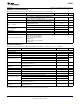
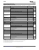


Table Of Contents
- FEATURES
- SOFTWARE FEATURES
- APPLICATIONS
- CC2541 WITH TPS62730
- DESCRIPTION
- ABSOLUTE MAXIMUM RATINGS
- RECOMMENDED OPERATING CONDITIONS
- ELECTRICAL CHARACTERISTICS
- GENERAL CHARACTERISTICS
- RF RECEIVE SECTION
- RF TRANSMIT SECTION
- CURRENT CONSUMPTION WITH TPS62730
- 32-MHz CRYSTAL OSCILLATOR
- 32.768-kHz CRYSTAL OSCILLATOR
- 32-kHz RC OSCILLATOR
- 16-MHz RC OSCILLATOR
- RSSI CHARACTERISTICS
- FREQUENCY SYNTHESIZER CHARACTERISTICS
- ANALOG TEMPERATURE SENSOR
- COMPARATOR CHARACTERISTICS
- ADC CHARACTERISTICS
- CONTROL INPUT AC CHARACTERISTICS
- SPI AC CHARACTERISTICS
- DEBUG INTERFACE AC CHARACTERISTICS
- TIMER INPUTS AC CHARACTERISTICS
- DC CHARACTERISTICS
- DEVICE INFORMATION
- TYPICAL CHARACTERISTICS
- APPLICATION INFORMATION
- References
- Additional Information
- Revision History

CC2541
www.ti.com
SWRS110D –JANUARY 2012–REVISED JUNE 2013
RF RECEIVE SECTION (continued)
Measured on Texas Instruments CC2541 EM reference design with T
A
= 25°C, VDD = 3 V, f
c
= 2440 MHz
PARAMETER TEST CONDITIONS MIN TYP MAX UNIT
250 kbps, GFSK, 160 kHz Deviation, 0.1% BER
Receiver sensitivity
(8)
–98 dBm
Saturation BER < 0.1% 0 dBm
Co-channel rejection Wanted signal -67 dBm –3 dB
±1-MHz offset, 0.1% BER, wanted signal –67 dBm 23
In-band blocking rejection ±2-MHz offset, 0.1% BER, wanted signal –67 dBm 28 dB
>2-MHz offset, 0.1% BER, wanted signal –67 dBm 29
Including both initial tolerance and drift. Sensitivity better than –67 dBm,
Frequency error tolerance
(9)
–150 150 kHz
250-byte payload. BER 0.1%
Symbol rate error Maximum packet length. Sensitivity better than –67 dBm, 250-byte
–80 80 ppm
tolerance
(10)
payload. BER 0.1%
250 kbps, MSK, 0.1% BER
Receiver sensitivity
(11)
–99 dBm
Saturation BER < 0.1% 0 dBm
Co-channel rejection Wanted signal -67 dBm –5 dB
±1-MHz offset, 0.1% BER, wanted signal –67 dBm 20
In-band blocking rejection ±2-MHz offset, 0.1% BER, wanted signal –67 dBm 29 dB
>2-MHz offset, 0.1% BER, wanted signal –67 dBm 30
Including both initial tolerance and drift. Sensitivity better than –67 dBm,
Frequency error tolerance –150 150 kHz
250-byte payload. BER 0.1%
Maximum packet length. Sensitivity better than –67 dBm, 250-byte
Symbol rate error tolerance –80 80 ppm
payload. BER 0.1%
ALL RATES/FORMATS
Spurious emission in RX.
f < 1 GHz –67 dBm
Conducted measurement
Spurious emission in RX.
f > 1 GHz –57 dBm
Conducted measurement
(8) Results based on standard-gain mode.
(9) Difference between center frequency of the received RF signal and local oscillator frequency
(10) Difference between incoming symbol rate and the internally generated symbol rate
(11) Results based on high-gain mode.
Copyright © 2012–2013, Texas Instruments Incorporated Submit Documentation Feedback 7
Product Folder Links: CC2541