
Data Sheet

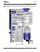

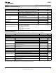
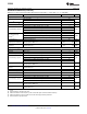


Table Of Contents
- FEATURES
- SOFTWARE FEATURES
- APPLICATIONS
- CC2541 WITH TPS62730
- DESCRIPTION
- ABSOLUTE MAXIMUM RATINGS
- RECOMMENDED OPERATING CONDITIONS
- ELECTRICAL CHARACTERISTICS
- GENERAL CHARACTERISTICS
- RF RECEIVE SECTION
- RF TRANSMIT SECTION
- CURRENT CONSUMPTION WITH TPS62730
- 32-MHz CRYSTAL OSCILLATOR
- 32.768-kHz CRYSTAL OSCILLATOR
- 32-kHz RC OSCILLATOR
- 16-MHz RC OSCILLATOR
- RSSI CHARACTERISTICS
- FREQUENCY SYNTHESIZER CHARACTERISTICS
- ANALOG TEMPERATURE SENSOR
- COMPARATOR CHARACTERISTICS
- ADC CHARACTERISTICS
- CONTROL INPUT AC CHARACTERISTICS
- SPI AC CHARACTERISTICS
- DEBUG INTERFACE AC CHARACTERISTICS
- TIMER INPUTS AC CHARACTERISTICS
- DC CHARACTERISTICS
- DEVICE INFORMATION
- TYPICAL CHARACTERISTICS
- APPLICATION INFORMATION
- References
- Additional Information
- Revision History

CC2541
SWRS110D –JANUARY 2012–REVISED JUNE 2013
www.ti.com
RF TRANSMIT SECTION
Measured on Texas Instruments CC2541 EM reference design with T
A
= 25°C, VDD = 3 V and f
c
= 2440 MHz
PARAMETER TEST CONDITIONS MIN TYP MAX UNIT
Delivered to a single-ended 50-Ω load through a balun using
0
maximum recommended output power setting
Output power dBm
Delivered to a single-ended 50-Ω load through a balun using
–23
minimum recommended output power setting
Programmable output power Delivered to a single-ended 50-Ω load through a balun using 23 dB
range minimum recommended output power setting
f < 1 GHz –52 dBm
Spurious emission conducted f > 1 GHz –48 dBm
measurement
Suitable for systems targeting compliance with worldwide radio-frequency regulations ETSI EN 300 328 and
EN 300 440 Class 2 (Europe), FCC CFR47 Part 15 (US), and ARIB STD-T66 (Japan)
Differential impedance as seen from the RF port (RF_P and RF_N)
Optimum load impedance 70 +j30 Ω
toward the antenna
Designs with antenna connectors that require conducted ETSI compliance at 64 MHz should insert an LC
resonator in front of the antenna connector. Use a 1.6-nH inductor in parallel with a 1.8-pF capacitor. Connect
both from the signal trace to a good RF ground.
CURRENT CONSUMPTION WITH TPS62730
Measured on Texas Instruments CC2541 TPA62730 EM reference design with T
A
= 25°C, VDD = 3 V and f
c
= 2440 MHz,
1 Mbsp, GFSK, 250-kHz deviation, Bluetooth™ low energy Mode, 1% BER
(1)
PARAMETER TEST CONDITIONS MIN TYP MAX UNIT
RX mode, standard mode, no peripherals active, low MCU activity, MCU
14.7
at 1 MHz
RX mode, high-gain mode, no peripherals active, low MCU activity,
16.7
MCU at 1 MHz
Current consumption mA
TX mode, –20 dBm output power, no peripherals active, low MCU activity, 13.1
MCU at 1 MHz
TX mode, 0 dBm output power, no peripherals active, low MCU activity,
14.3
MCU at 1 MHz
(1) 0.1% BER maps to 30.8% PER
32-MHz CRYSTAL OSCILLATOR
Measured on Texas Instruments CC2541 EM reference design with T
A
= 25°C and VDD = 3 V
PARAMETER TEST CONDITIONS MIN TYP MAX UNIT
Crystal frequency 32 MHz
Crystal frequency accuracy
–40 40 ppm
requirement
(1)
ESR Equivalent series resistance 6 60 Ω
C
0
Crystal shunt capacitance 1 7 pF
C
L
Crystal load capacitance 10 16 pF
Start-up time 0.25 ms
The crystal oscillator must be in power down for a guard
time before it is used again. This requirement is valid for
Power-down guard time 3 ms
all modes of operation. The need for power-down guard
time can vary with crystal type and load.
(1) Including aging and temperature dependency, as specified by [1]
8 Submit Documentation Feedback Copyright © 2012–2013, Texas Instruments Incorporated
Product Folder Links: CC2541