IG700 User’s Installation and Configuration Manual
Copyright © 2011 This manual is copyrighted, with all rights reserved. Under the copyright laws, this manual may not, in whole or in part, be copied, photocopied, reproduced, translated or converted to any electronic medium or machine readable form without prior written consent. Limited Warranty Under all circumstances this manual should be read attentively before installing and/or using the product.
Table of Contents INTRODUCTION ....................................... ....................................... 1 CHAPTER 1 PRODUCT SAFETY ............. 1 1.1 Safety & Caution ............................1 1.2 FCC Warning .................................3 1.3 Use of The IG-700 .........................4 1.4 IG-700 Unpacking..........................5 1.5 Mounting ........................................6 1.6 USB Interface ................................7 1.7 Configuration .................................
Introduction IG-700 is a cutting-edge gun-type barcode scanner which is designed specifically for retail market. We add on more user-friendly functions with detachable cable that makes it more easily to be operated by the customers. The new IG-700 supports middle to long range operation. It is absolutely a high performance gun-type scanner. It provides the customer with the most efficient solution in the market.
Chapter 1 Product Safety 1.1 SAFETY & CAUTION 1. Please read the following safety statement carefully. 2. Please preserve this user manual for reference. 3. Before cleaning the IG-700, the user must unplug all power. Do not use liquid or spray type of detergent to clean the scanner. Please use dampish cotton cloth to clean the scanner. 4. The power cord must be set nearby the scanner for easier power connection. 5. Keep the product dry to avoid short circuit. 6.
(a) The damage of wire or pin of power supply. (b) The liquid infiltrates in the product. (c) The exposure of the product in the wet environment. (d) The equipment cannot work well. (e) Any obvious damage that causes the scanner to fail working normally. 12. Do not storage the scanner in where the temperature lower than -20°C (-4°F) or higher than +70°C (158°F).
1.2 FCC WARNING This product complies with the requirements in Part 15 of FCC. Any operation must comply with the conditions below: (a) The equipment will not cause any severe interference. (b) The equipment can avoid any interference from environment. Statement: This product is classified as an A class product. This product may cause some interference with the environment surrounded; the user may have to do something to avoid interference under this circumstance.
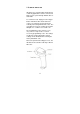
1.3 USE OF THE IG-700 IG-700 is very contemporarily designed and commonly applicable. It can be connected to POS or Host system through RS232 cable or USB cable. To read a bar code, simply press the trigger button and aim the blue beam at the bar codes. It is required to position the beam vertically intersecting with the bar codes. The user will hear one beep, and the green LED will light on to confirm a successful scan. The programming of the scanner is very easy.
1.4 IG-700 UNPACKING Unpack the IG-700 as follows: 1. Take the scanner and its accessories out of the box. 2. Remove the packing material. 3. Check the packing list to make sure you receive all of the items ordered. Standard Shipment Package (a) IG-700 Area Imager Handheld Bar code Scanner (b) Communication Cable (c) Power Adaptor (optional) (d) User Manual 4. Check the IG-700 and accessories for any physical damage. ATTENTION The packing box should be used whenever the IG-700 is transported for service.
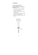
1.5 MOUNTING The new IG-700 is designed for costumer-installation. Once the user unpacks all components, he/she can start installing the scanner. The following are the steps for installation: 1. Connect the scanner to the supplied interface cable (RJ45 side). 2. Connect the scanner interface cable to the POS system. 3. Connect the power supply cable (RS232 interface) to power cable jack. 4. Plug the power supply cable into the AC outlet.
1.6 USB INTERFACE Like all USB devices, the user must install the driver on the host system before connecting the IG-700 with USB virtual com interface. Please contact Champtek Technical Support Department if the user needs the USB driver. The user can also download the USB driver from the web site listed below: http://www.champtek.com/ 1.
1.7.2 Changing Scanner Settings with Utility Tool Champtek provides this user manual with the most common used programming codes; it is possible that the user does not have enough programming codes to meet his/her desired operational settings. This tool can be used with the following operation systems: Windows98, Windows2000, Windows XP and Windows Vista. This utility tool can be delivered upon request. Please contact Champtek Technical Support Department.
Chapter 2 Configuration The configuration change will take effect immediately and save to memory. 2.
2.
2.
2.
13
14
15
16
17
18
19
20
2.
2.
2.7 PREFIX 2.
24
Appendices A.READABLE SYMBOLOGIES Symbologies Aztec Codabar Codablock Code 11 Code 39 Code 93 Code 128 Composite DataMatrix GS1 DataBar (RSS) Interleaved 2 of 5 Matrix 2 of 5 MaxiCode Marco PDF417 Micro PDF417 MSI Plessey NEC2 of 5 PDF417 Post Codes(Australian, Japan, KIX, Postnet, Planet, Royal) QR Code Telepen UPC/EAN Default Enable V V V V V V V V V V V V B.TECHNICAL SPECIFICATIONS Physical Characteristics Body Weight Approx. 150 gm Material ABS Plastic Connector RJ45C 10Pins Dimension 82.
Operational Light Source Resolution Scan Angle Visible Red Light 650nm + 20nm 1280 Horizontal x 960 Vertical Pixels, 256 Gray Levels. 30° Horizontal, 20° Vertical on high density field 50° Horizontal, 33.
Environmental Operating Temp. 0°C to 50°C (32°F to 122°F) Storage Temp. -20°C to 70°C (-4°F to 158°F) Relative Humidity 0 to 95% non-condensing Ambient Light Work in lighting conditions from 0 to 100,000 lux Regulatory of Compliance FCC CE C.SCAN MAP Typical Reading Range (Centimeters) Symbology Density Minimum Maximum Distance Distance Inches(mm) Inches(mm) Code 39 3mil 3.9"(100) 4.7"(120) 7.5mil 2.0"(50) 8.0"(205) 13mil 2.0"(50) 10.8"(275) Data Matrix 4.2mil 3.7"(9.5) 4.
28