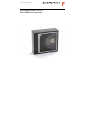
user’s manual Scantech Pollux P-4010 Bar code laser scanner
Pollux_UserM_Deel1.
Pollux_UserM_Deel1.qxd 14-11-2002 09:05 Pagina b Copyright © 2007, Scantech-ID BV. This manual is copyrighted, with all rights reserved. Under the copyright laws, this manual may not, in whole or in part, be copied, photocopied, reproduced, translated or converted to any electronic medium or machine readable form without prior written consent of Scantech-ID BV. Limited Warranty Under all circumstances this manual should be read attentively, before installing and/or using the product.
Pollux_UserM_Deel1.qxd 14-11-2002 09:05 Pagina c Table of contents Preface Chapter 1 Chapter 2 Chapter 3 Appendices i The Pollux P-4010 1 1.1 Unpacking the Pollux P-4010 1.2 Scanning bar codes with the Pollux P-4010 1.3 Scanner labelling 1.4 Maintaining the scanner 1.5 Controlling the scanner from the POS system 2 4 6 9 9 Installing the Pollux P-4010 11 2.1 Installing the scanner on a counter surface 13 Mounting options Pollux P-4010 17 3.1 Flyby mode scanning: right to left 3.
Pollux_UserM_Deel1.qxd 14-11-2002 09:05 Pagina d Preface The Pollux P-4010 is an innovative, high performance food retail scanner, combining unequalled performances with enormous installation flexibility. It has a unique four-directional sealed optical assembly, allowing it to be turned inside the fixed scanner housing. This new benchmark for vertical supermarket and hypermarket scanning ensures an ergonomic and user-friendly implementation wherever it is installed.
Pollux_UserM_Deel1.
Pollux_UserM_Deel1.qxd 14-11-2002 09:05 2 Pagina 2 The Pollux P-4010 1.1 UNPACKING THE POLLUX P-4010 Remove the scanner and its accessories from the box and packing material. Refer to the packing list to make sure you have received all the items ordered. Visually inspect the scanner and accessories for any evidence of physical damage. Refer to the figure on page 6 to locate the interface label and make sure that the scanner interface corresponds with the host system interface.
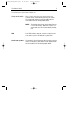
Pollux_UserM_Deel1.qxd 14-11-2002 09:05 Pagina 3 The Pollux P-4010 3 The various parts of the Pollux P-4010 are: Sleep mode switch - When a sleep mode time-out is programmed, the scanner can be re-activated by pressing this switch. The sleep-mode feature is programmable with the menu labels from the Configuration Guide. NOTE: The default value for the sleep mode time-out is set to 30 minutes. When the scanner is in sleep mode, the LED is intermittently flashing red.
Pollux_UserM_Deel1.qxd 14-11-2002 09:05 Pagina 4 4 The Pollux P-4010 1.2 SCANNING BAR CODES WITH THE POLLUX P-4010 The Pollux P-4010 is an omni-directional scanner featuring a 5 directional scan field with a 20 lines scan pattern. The scanner's scan volume is illustrated in the figure below. The optimal reading zone lies between 1 and 9 cm from the scanner window, but bar codes can be read up to 30 cm (11.8 in.) from the scanner window. The scanner can be used in either fly by or presentation mode.
Pollux_UserM_Deel1.qxd 14-11-2002 09:05 Pagina 5 The Pollux P-4010 5 Presentation mode: top view front view POLLUX 1 cm optimal reading zone 9 cm 30 cm Scanning a bar code label in presentation mode is also very simple: present the product’s bar code label to the scanner as illustrated in the figure below. scanner in presentation mode POLLUX 1. Move the label to the scanner. ☞ sp che ecial o win ff g-g er um Bar code is read (green led). 2. Move the label from the scanner.
SH02-001_PolluxU this page: 20-10-2003 10:33 Pagina 6 6 The Pollux P-4010 1.3 SCANNER LABELLING Two labels are present on the housing of the Pollux P-4010 as indicated in the figure below. Two labels are also visible through the scanner window. All labels are attached by the manufacturer and should not be removed. Software Part No: WO1: Serial no.
Pollux_UserM_Deel1.qxd 14-11-2002 09:05 Pagina 7 The Pollux P-4010 7 Laser safety English: The P-4010 scanner complies with safety standard IEC 825-1 (1993) for a Class I laser product. It also complies with U.S. 21CFR1040 as applicable to a Class IIa laser product. Avoid long term viewing of direct laser light. German: Der Strichcode-Scanner P-4010 entspricht den Sicherheitsvorschriften nach IEC 825-1 (1993) für ein Laserprodukt der Klasse I. Er entspricht auch U.S.
Pollux_UserM_Deel1.qxd 8 14-11-2002 09:05 Pagina 8 The Pollux P-4010 Norwegian: P-4010 skanneren er i samsvar med sikkerhetsstandarden IEC 825-1 (1993) for laserprodukter i klasse I. Den er også i samvar med U.S. 21CFR1040 for laserprodukter i klasse IIa. Unngå å se langvarig på direkte laserlys. Italian: Lo scanner P-4010 è conforme alle norme di sicurezza IEC 825-1 (1993) relative ad un prodotto laser di Classe 1. È inoltre conforme alla norma U.S.
Pollux_UserM_Deel1.qxd 14-11-2002 09:05 Pagina 9 The Pollux P-4010 9 Adjustments: Do not attempt any adjustments to or alteration of this product. Do not remove the scanner’s protective housing. There are no user-serviceable parts inside. CAUTION: Use of controls or adjustments or performance of procedures other than those specified herein may result in hazardous laser light exposure. 1.4 MAINTAINING THE SCANNER The Pollux P-4010 scanner requires little maintenance.
Pollux_UserM_Deel1.
Pollux_UserM_Deel1.
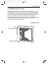
Pollux_UserM_Deel1.qxd 14-11-2002 09:05 12 Pagina 12 Installing the Pollux P-4010 Depending on the way you want to use the Pollux P-4010, the scanner can be installed fixed on a counter surface or sunk into the counter surface. The Pollux can be installed in two different ways, scanner housing Landscape or scanner housing Portrait (see the illustrations below). Refer to chapter 3 for the various mounting options of the Pollux.
Pollux_UserM_Deel1.qxd 14-11-2002 09:05 Pagina 13 Installing the Pollux P-4010 13 Instructions for installation on a counter surface are given in Section 2.1. Due to many POS systems on the market, a large number of communication cables is available. Make sure that you have the right cable to connect the scanner to your POS or computer. NOTES ■ The scanner and the host system must be switched off before starting the installation of the scanner.
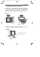
Pollux_UserM_Deel1.qxd 14-11-2002 09:05 Pagina 14 14 Installing the Pollux P-4010 4. Locate the small hole at the back cover of the scanner. Remove the back 1. cover by pressing it with a coin as indicated in the figure. insert insert 5. Lead the power supply cable and communication cable through the hole in the counter. 6.
Pollux_UserM_Deel1.qxd 14-11-2002 09:05 Pagina 15 Installing the Pollux P-4010 15 AUX INTERFACE PORT 2 INTERFACE PORT 1 POWER Interface port 1. Connect the communication cable to this port if the host system features the RS232C or IBM RS 485 interface AUX AUX INTERFACE PORT 2 INTERFACE PORT 1 INTERFACE PORT 2 INTERFACE PORT 1 POWER POWER Interface port 2.
Pollux_UserM_Deel1.qxd 14-11-2002 09:05 Pagina 16 16 Installing the Pollux P-4010 AUX INTERFACE PORT 2 INTERFACE PORT 1 POWER 7. Place the scanner on the vertical mount as illustrated in the figure. SCANNER FRONT 8. Reposition the back cover of the scanner. 9. Power on the scanner by connecting the IEC power cord to the AC/DC power supply and plugging the AC power cord into an AC power outlet. Switch on the host system.
Pollux_UserM_Deel1.
Pollux_UserM_Deel1.qxd 14-11-2002 09:05 18 Pagina 22 Mounting options Pollux P-4010 The ability to turn the optical assembly of the Pollux provides a large number of mounting options. This chapter will help you find the best mounting option for your application. (For information on turning the optical assembly, please refer to the Pollux Service Manual. Authorized personnel only). The Pollux P-4010 can be installed: - fixed on a counter surface or - sunk into the counter surface.
Pollux_UserM_Deel1.qxd 14-11-2002 09:05 Pagina 23 19 Mounting options Pollux P-4010 3.1 FLYBY MODE SCANNING: RIGHT TO LEFT To scan from Right to Left, install the scanner housing by: a. landscape orientation or b. portrait orientation. a. Scanning from Right to Left, scanner housing landscape orientation On counter surface 3.
Pollux_UserM_Deel1.qxd 14-11-2002 20 09:05 Pagina 24 Mounting options Pollux P-4010 b. Scanning from Right to Left, scanner housing portrait orientation On counter surface 3.1b1 POLLUX special offer chewing-gum Cable supply Not recommended. The need to lift the products being scanned increases. Sunk into counter surface 3.
Pollux_UserM_Deel1.qxd 14-11-2002 09:05 Pagina 25 21 Mounting options Pollux P-4010 3.2 FLYBY MODE SCANNING: LEFT TO RIGHT To scan from Left to Right, install the scanner housing by: a. landscape orientation or b. portrait orientation. a. Scanning from Left to Right, scanner housing landscape orientation On counter surface 3.
Pollux_UserM_Deel1.qxd 14-11-2002 09:05 22 Pagina 26 Mounting options Pollux P-4010 b. Scanning from Left to Right, scanner housing portrait orientation On counter surface 3.2b1 special offer chewing-gum POLLUX Cable supply Not recommended. The need to lift the products being scanned increases. Sunk into counter surface 3.
Pollux_UserM_Deel1.qxd 14-11-2002 09:05 Pagina 27 23 Mounting options Pollux P-4010 3.3 PRESENTATION MODE SCANNING To scan in presentation mode, install the scanner housing by: a. landscape orientation or b. portrait orientation. a. Scanning in presentation mode, scanner housing landscape orientation On counter surface 3.3a1 POLLUX fer ial of m spec ing-gu chew 1 Cable supply 2 Product flow Not recommended. Due to a minimized scan pattern.
Pollux_UserM_Deel1.qxd 14-11-2002 09:05 24 Pagina 28 Mounting options Pollux P-4010 b. Scanning in presentation mode, scanner housing portrait orientation On counter surface 3.3b1 POLLUX special offer chewing-gum 1 2 Product flow Cable supply Sunk into counter surface 3.3b2 POLLUX special offer chewing-gum 1 2 Product flow Cable supply Not recommended. Due to a minimized scan pattern.
Pollux_UserM_Deel2.qxd 14-11-2002 10:07 Pagina 1 Appendices A. Connector types and pin definitions B. Technical Specifications C.
Pollux_UserM_Deel2.qxd 14-11-2002 10:07 Pagina 30 26 Appendices A. CONNECTOR TYPES AND PIN DEFINITIONS There are two dual interface versions of the Pollux available: RS232C/OCIA and IBM RS485/Keyboard Wedge. The various pin definitions for the applicable Data port are given on page 31. The connector to be used for the port is indicated below.
Pollux_UserM_Deel2.qxd 14-11-2002 10:07 Pagina 31 27 Appendices Pin definition for dual interface version RS232C-OCIA RS232C interface Data port 1 OCIA interface Data port 2 Pin Description Direction Pin Description Direction 1 CTS input 1 IFID input 2 RXD input 2 DATA output 3 TXD output 3 DATA RTN output 4 RTS output 4 CLOCK IN input 5 GND - 5 GND - 6 Not Con.
Pollux_UserM_Deel2.qxd 14-11-2002 10:07 Pagina 32 28 Appendices B. TECHNICAL SPECIFICATIONS Electrical Power supply voltage DC input to scanner 100 - 250 V ac, 50/60 Hz + 12 V dc, 600 mA - 12 V dc, 75 mA + 5 V dc, 350 mA Depending on scanner version Interface port 1: RS232 or IBM RS485 Interface port 2: OCIA or KBW Secondary scanner (250 mA max.
Pollux_UserM_Deel2.qxd 14-11-2002 10:07 Pagina 33 29 Appendices Environmental Operating temperature Humidity 0° C ~ 40° C 0% ~ 95% RH (non-condensing) Safety Laser safety Electrical safety Flammability rate IEC 825-1 (1993) Class I, U.S. 21CFR1040 Class IIa EN 60950 second edition UL1950 (third edition), c-UL (according CSA22.2.
Pollux_UserM_Deel2.qxd 14-11-2002 30 10:07 Pagina 34 Appendices C. TROUBLESHOOTING This section contains information on solving problems you may encounter when using the scanner. If troubles occur, take a moment to read the information in this section. However, before referring to the diagnostic tips make sure that the scanner is installed as described in Chapter 2 and that all cables are properly connected.
Pollux_UserM_Deel2.qxd 14-11-2002 10:07 Pagina 35 31 Appendices Problem The scanner is on but a bar code cannot be read. The LED is red. Diagnostic Tips ■ The scanner window is dirty. Clean the ■ scanner window as described in the ■ Maintenance section. ■ The presented bar code type is not ■ enabled. Select the bar code type with ■ the Configuration Guide. ■ The scanner is disabled by the host. ■ Refer to Section 1.5. ■ The bar code type you presented to the ■ scanner is not supported by the Pollux.
Pollux_UserM_Deel2.qxd 14-11-2002 10:07 32 Pagina 36 Appendices Problem The LED remains green. Diagnostic Tips ■ The scanner is continuously seeing a bar code. Remove all bar code labels from the scan volume of the scanner and try again. ■ The scanner cannot send the data to the host system. There is no proper handshaking between the scanner and the host. Scanner buffer is full. Make sure that all cables are connected and your host system is ready to receive data.
Scanner outline TEMPLATE B: SCANNER HOUSING PORTRAIT SCANNER FRONT Hole in counter surface for cable supply TEMPLATE A: SCANNER HOUSING LANDSCAPE SCANNER FRONT Scanner outline Hole in counter surface for cable supply
Scantech-ID BV Amersfoortsestraat 124 3769 AN Soesterberg The Netherlands Phone: Fax: E-mail: Internet: +31 (0 )33 469 84 00 +31 (0 )33 465 06 15 info@scantech-id.com www.scantech-id.