
User Manual


26 Appendices
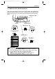
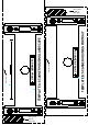
AMP 5-554169-1
male connector
pin 8
pin 1
POWER SUPPLY PORT
pin 8
pin 1
pin 8
pin 1
AMP 5-554170-1
male connector
front view:
pin 8
pin 1
IINTERFACE PORT 1
A
U
X
IN
T
E
R
F
A
C
E
IN
T
E
R
F
A
C
E
P
O
W
E
R
P
O
R
T
2
P
O
R
T
1
INTERFACE PORT 2
pin 10
pin 1
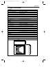
Stewart 940SP301010RK2
male connector
front view:
pin 10
pin 1
AUX PORT
Description
+5VDC (250 mA max.)
CTS
RXD
Reserved
GND
Reserved
Aux port
RTS
Pin
1
2
3
4
5
6
7-10
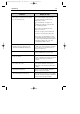
A. CONNECTOR TYPES AND PIN DEFINITIONS
There are two dual interface versions of the Pollux available: RS232C/OCIA and
IBM RS485/Keyboard Wedge. The various pin definitions for the applicable Data
port are given on page 31. The connector to be used for the port is indicated
below.
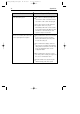
■ To activate Data port 2 (OCIA or KBW interface), follow this sequence:
1. Plug in the appropriate interface cable and then power up the scanner.
2. Scan the following codes from the Configuration Guide:
- Open the scanner Programming Mode by scanning code 1.1
- Return to factory default settings by scanning code 1.3
IMPORTANT
Pollux_UserM_Deel2.qxd 14-11-2002 10:07 Pagina 30