User Guide November 2009 CAT5/5e KVM Extender Range Standard and Serial Models Standard Kits Model SDLink1 Model SDLink2 Model SDLink1/SU Model SDLink2/SU Serial Kits Model SDLink1/S Model SDLink2/S Remote Units Model SDLink/R Model SDLink/RS Model SDLink/RSU
Notices Cautions and Notes The following symbols are used in this guide: CAUTION. This indicates an important operating instruction that should be followed to avoid any potential damage to hardware or property, loss of data, or personal injury. NOTE. This indicates important information to help you make the best use of this product. Copyrights and Trademarks ©2004/2009. All rights reserved. This information may not be reproduced in any manner without the prior written consent of the manufacturer.
2 CAT5/5e KVM Extender Range Safety Precautions and Installation Guidelines To ensure reliable and safe long-term operation please note the following installation guidelines: • Do not use to link between buildings. • Only use in dry, indoor environments. • If the building has 3-phase AC power, try to ensure that equipment connected to the Local and Remote Units is on the same phase. • Try not to route the CATx link cable alongside power cables.
3 Contents Contents 1. Quick Setup 5 2. Overview 6 3. 4. 5. 6.
4 CAT5/5e KVM Extender Range Appendix A: Example Applications 33 Appendix B: Rack Mount Options 36 Appendix C: Advanced Cabling Issues (Skew) 37 Appendix D: Serial Port Setup and Operation 39 Appendix E: Obtaining Technical Support 42 Appendix F: Specifications 43 Appendix G: EU Regulatory Compliance 46 Appendix H: North American Regulatory Compliance 47 Appendix I: 47 Disclaimer
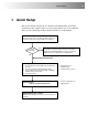
Quick Setup 1. Quick Setup This section briefly describes how to install your KVM extender system and optimize the video signals. Unless you are an experienced user, we recommend that you follow the full procedures described in the rest of this manual. .
6 CAT5/5e KVM Extender Range 2. Overview Introduction The SDLink products described in this manual enable high-resolution video, PS/2 keyboard and mouse or SUN keyboard, stereo audio, and serial port signals to be communicated up to 300m over over Category 5, 5e or higher CATx cable. A basic KVM extension system comprises a Local Unit (transmitter) and a Remote Unit (receiver). The Local Unit connects directly to the computer (or a KVM switch system) using the supplied cable(s).
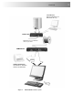
Overview Local Access SDLink2, SDLink2/S and SDLink2/SU kits only. LOCAL Unit KVM extension over CAT5/5e cables up to 300m.
8 CAT5/5e KVM Extender Range Features All members of the SDLink product family described here offer the following features: • Support for high video resolution over extended distances: 1600x1200@60Hz up to 65m 1280x1024@75Hz up to 120m 1024x768@75Hz up to 300m • Adjustable video equalization compensates for loss of image quality over extended cable lengths. • Fully buffered signals to ensure consistent remote operation of your PC.
Overview Product Range This manual describes the following nine products from the SDLink range: KVM Extension kits SDLink1 Single Video Channel, PS/2 KB & Mouse Local Unit (Single Access) + Remote Unit SDLink2 Single Video Channel, PS/2 KB & Mouse Local Unit (Dual Access) + Remote Unit SDLink1/SU Single Video Channel, SUN KB/Mouse Local Unit (Single Access) + Remote Unit SDLink2/SU Single Video Channel, SUN KB/Mouse Local Unit (Dual Access) + Remote Unit KVM and Serial Extension kits SDLink1/S Sin
10 CAT5/5e KVM Extender Range Compatibility Interface Compatibility • • • • • PS/2 Keyboard: PS/2 models are compatible with all standard keyboards. Certain keyboards with enhanced features may also be supported with custom firmware. PS/2 Mouse: PS/2 models are compatible with all standard 2-button, 3button and wheel mice. To connect to a PC that does not have a PS/2 mouse port, an active serial converter is required - Model: Mdapt (PS/2). SUN keyboard: SDLink1/SU, SDLink2/SU and SDLink/RSU only.
Overview How to Use This Guide This guide describes the installation and configuration of Standard and Serial members of the SDLink range of KVM extenders. Although the connection and operation of these systems is relatively straightforward, you should consider the following before getting started: Connection & Compatibility If you have purchased an SDLink Extender kit, this will contain all the cables required to connect the Local Unit to your PC or KVM switch.
12 CAT5/5e KVM Extender Range 3. Installation For first-time users, we recommend that you carry out a test placement, confined to a single room, before commencing full installation. This will allow you to identify and solve any cabling problems, and experiment with the KVM extender system more conveniently. Package Contents You should receive the following items in your extender package. If anything is missing, please refer to Appendix E: Obtaining Technical Support, page 42. • Extender Remote Unit.
Installation Interconnection Cable Requirements To connect the Local and Remote Units you will need CATx (any category 5, 5e, 6 or higher) cable terminated with RJ45 plugs. Please note that shielded cable is advised to maintain regulatory EMC compliance. Interconnect cables must be solid-core type. Stranded patch cable will give poor results over longer distances. The pairing of the cable and pinning of its connectors should normally be in accordance with EIA-568B.
14 CAT5/5e KVM Extender Range Remote Unit Configuration Setting the Cable Length Jumpers If your application uses an interconnection cable less than 75m in length, you can continue to the next section. SDLink Remote Units incorporate video equalization circuitry, allowing you to compensate for the loss in image quality that occurs when video signals are transmitted along lengthy CATx cables.
Installation 4. Set the three cable length jumpers as follows: Interconnect Cable Length (m) 0 – 100 Jumper Position (as viewed from front, with RJ45 connector towards you) No jumpers (default) 100 – 200 200 – 300 If you are at the top end of a cable range, and you are using a high screen resolution (1024x768 or higher), you may achieve better quality video compensation by selecting the next cable length range. Ensure that all three jumpers are set to the same position.
16 CAT5/5e KVM Extender Range Connecting the Remote Unit To install a Remote Unit: 1. Switch off all devices. 2. Connect your keyboard, monitor(s) and mouse to the Remote Unit as shown in Figure 3 (Standard), Figure 4 (SUN) or Figure 5 (Serial). These ports may also be attached to the CPU side of a KVM switch in order to have a remote CPU. However, if you are attempting to use the extender between cascaded KVM switches this may not work. Please contact Technical Support to discuss your application. 3.
17 Installation Connect to monitor. Figure 4 Connect to monitor. Connect PS/2 keyboard and mouse. Connect approved 9V power supply. SDLink Serial Remote Unit (SDLink/RS – also supplied with SDLink1/S and SDLink2/S kits) – rear view Interconnect – carries video and data signals. Connect to Interconnect port on Local Unit using CATx cable. Figure 6 Connect approved 9V power supply.
18 CAT5/5e KVM Extender Range Local Unit Installation To install a Local Unit: 1. Switch off the PC and any peripheral devices before connection. 2. Using the supplied CPU KVM cable(s), connect the keyboard, monitor(s) and mouse connectors on the computer (or KVM switch) to the corresponding connectors on the Local Unit as shown in Figure 7 (Standard), Figure 8 (SUN) or Figure 9 (Serial). Ensure that you attach the keyboard and mouse connectors to the correct ports.
19 Installation Connect to computer’s video output. Connect to Local monitor. Connect to computer’s SUN keyboard port. SDLink1/SU and SDLink2/SU Connect to SUN keyboard SDLink2/SU only Figure 8 SDLink SUN Local Unit - rear view Connect to Local monitor. Connect to serial port on computer. SDLink2/S only Connect to Local PS/2 keyboard and mouse. Connect to computer’s primary video, PS/2 keyboard and mouse ports using supplied cable.
20 CAT5/5e KVM Extender Range Connection to Rack Mount Hub Local Units PS/2 SDLink Remote Units are compatible with SDRK Rackmount Extender Hub Local Units belonging to the same family: SDLink Remote Units Compatible Local Rack Hubs SDLink1, SDLink2, SDLink/R SDRK/6, SDRK/6D, SDRK/12 SDLink1/S, SDLink2/S, SDLink/RS SDRK/6S, SDRK/6SD A simple example of the use of a rackmount hub Local Unit is shown in Figure 11.
Remote Unit Configuration & Operation 4. Remote Unit Configuration & Operation Catx cables are specifically designed for networking applications and not for transmitting analog video. Your CATx KVM extender includes, and requires, advanced technology to enable its use at high screen resolutions. This section describes how to optimize the video signal, configure the Extender system and operate the Remote Unit.
22 CAT5/5e KVM Extender Range Video Adjustments SDLink Remote Units feature a number of correction tools to simplify video optimization. This procedure is straightforward and only needs to be carried out once. Please note that cable equalization cannot be exact – the remote image will never be as sharp as the original. The KVM Extender’s equalization system produces good results for short to medium length cables (<150m).
Remote Unit Configuration & Operation 2. Turn the PEAK and EQ controls on the Remote Unit fully anti-clockwise. The image quality may be poor at this point. 3. Use the EQ control to adjust video equalization. If the video signal is undercompensated, you will notice black smearing on the right-hand edge of large horizontal objects such as title bars. If it is overcompensated, horizontal edges may become bright and too sharp. Rotate the EQ control clockwise until these effects disappear.
24 CAT5/5e KVM Extender Range Other Remote Configuration & Operation Options Scroll Lock Function Standard and Serial SDLink Remote Units redefine the function of the Scroll Lock key for system commands. Press the Scroll Lock key to reset the keyboard and mouse. You may need to do this if a hot-plugged keyboard or mouse does not initialize correctly. You can restore normal Scroll Lock activity by setting switch 4 on the SW1 DIP switch block to OFF (see Figure 13).
Remote Unit Configuration & Operation Remote Console Commands Standard and Serial Remote Units use the Scroll Lock key for system commands. The following table lists the commands available at a remote console: Command Key Sequence Reset Keyboard and Mouse PS/2 versions: SUN versions: + Reset the remote console’s keyboard and mouse. You may need to do this if you have plugged a keyboard or mouse into a powered Remote Unit and it has not initialized correctly.
26 CAT5/5e KVM Extender Range 5. Local Unit Operation Overview You need to read this section if you have purchased an extender system kit containing both a Local and Remote Unit. For more information about serial port operation, see Appendix D: Serial Port Setup and Operation, page 39. Keyboard and Mouse Emulation Local Units have keyboard and mouse emulation.
Local Unit Operation Operation of Dual Access Local Units Models SDLink2, SDLink2/S and SDLink2/SU offer dual access with a second console at the Local Unit. This operates on a first-come, first-served basis. When one console is in use, the system blocks out the other console until there is no keyboard or mouse use at the active console for a set time: the Inactivity Timeout Period. Thereafter, any keyboard (and, optionally, mouse) action at the other console switches console activity.
28 CAT5/5e KVM Extender Range Command Summary On a dual access system, you can issue the following commands at the local console: Command Key Sequence Activate Console Any key and (optionally) mouse action Gain control of CPU from remote console. Only operates if inactivity timeout period has expired. Start/End Private Mode PS/2 versions: SUN versions: + Start/End ‘Private Mode’ at local console.
Troubleshooting 6. Troubleshooting Video The image is not sharp, or is badly smeared. Have you adjusted the video equalization? Follow the instructions on page 21. Check the Interconnect cable between the Remote and Local Units. Is it of the recommended type (see page 13)? Is it intact along its entire length and securely connected at both ends? Is it wired correctly? Ensure that all video connections throughout the system are attached securely.
30 CAT5/5e KVM Extender Range The PC won’t boot into the correct graphics mode The extender includes DDC emulation for all standard resolutions and there should not normally be any issues. For non-standard resolutions, you will need to explicitly set the resolution in your operating system configuration ignoring the DDC data read from the Local Unit. Contact Technical Support if you have problems selecting your required graphics mode. Note: DDC emulation is not provided on SUN extender models.
Troubleshooting Keyboard & Mouse When I am typing, I get wrong or missing characters on the screen. Your keyboard may be in the wrong mode. Use the appropriate commands to reset the keyboard and mouse as described in the sections covering local and remote operation. The PC comes up with ‘keyboard error’. Press or . If the keyboard now operates correctly, you need to adjust the BIOS setup to disable keyboard testing during booting. The system does not detect a PS/2 mouse.
32 CAT5/5e KVM Extender Range General Questions Is it possible to use a cable longer than 300m? It might be possible to use a cable of up to 500m at lower resolutions. However, we do not recommend this and cannot guarantee that it will work. Can the extender be daisy chained? In certain circumstances, it is possible to cascade extenders, though we do not recommend doing so. Careful consideration needs to be given to extender setup, and the electrical environment.
Appendix A: Example Applications Appendix A: Example Applications This section illustrates three specific applications using SDLink extender units: • Simple system using SDRK/6S Hub and SDLink/RS Remote Units to extend serial and KVM for up to six PCs (Figure 14). • Two remote serial touch screens with local access through a KVM switch (Figure 15) using two SDLink2/S kits. • Information distribution system sharing a single PC at up to six remote locations (Figure 16).
34 CAT5/5e KVM Extender Range Local Units KVM Switch Take KVM and serial signals from two CPUs. Local access ports connect to single KVM console through switch. Two SDLink2/S kits Remote Units Connect to touch screens.
Appendix A: Example Applications SDRK/6D Extender Hub CPU connects to Port 1. Local access ports are daisy-chained to allow operation from any console and/or video to be distributed to multiple locations. 5V PSU SDLink/R Remote Units connect to KVM consoles.
36 CAT5/5e KVM Extender Range Appendix B: Rack Mount Options Extender units can be mounted in a 19” rack using the mounting kits: • SDBR1 • SDBR2 (for Local Units supplied with SDLink2/S only) Each kit consists of two angled brackets. To mount a unit: 1. Remove the two screws from one side of the unit. 2. Match up the lower pair of holes on a bracket with the vacant screw holes on the side of the unit. 3. Using the original screws, fasten the mounting brackets to the side of the unit. 4.
Appendix C: Advanced Cabling Issues (Skew) Appendix C: Advanced Cabling Issues (Skew) This section discusses skew and how to minimize its effects. What is Skew? Each color in the RGB (Red, Green, Blue) video signal is sent down a separate pair of wires in the Interconnect cable. On many cables, the twist rates differ and this leads to each color arriving at a slightly different time and therefore spreading out on the screen.
38 CAT5/5e KVM Extender Range You can measure pair lengths with a LAN cabling tester (TDR) or view pairs by stripping back a small piece of cable and viewing how tightly the pairs are twisted. The most tightly twisted pair is the slowest (longest) and the loosest pair the fastest (shortest). You can also observe relative delays using the test card. Some cables have a ‘3+1’ construction where three pairs closely match.
Appendix D: Serial Port Setup and Operation Appendix D: Serial Port Setup and Operation Applies to SDLink1/S, SDLink2/S and SDLink/RS only The default settings for serial extension (9600bps, 8 data bits, no parity, 1 stop bit, RTS/CTS and DTR/DSR loopback) are suitable for the majority of applications. This appendix describes how you can adjust the baud rate and hardware flow control for specialist applications.
40 CAT5/5e KVM Extender Range Baud Rate You can set the baud rate for serial communication across the extender system at 19200, 9600 (the default) or 1200 baud. All Local Units are supplied to accept a baud rate of either 9600 or 19200. No configuration of the Local Unit is required unless you want to operate at 1200 baud (see below). Changing the Baud Rate to 19200/9600 All Remote Units are supplied with the baud rate preset at 9600.
Appendix D: Serial Port Setup and Operation In most cases, we recommend that you use PS/2 mouse devices with an SDLink extender system. If you have a PC that does not have a PS/2 mouse port: • Plug a PS/2 mouse into the Remote Unit. • Use an Mdapt (PS/2) Serial Mouse Converter to connect the PC to your Local Unit. The drivers supplied with certain Wacom Graphics Tablets dynamically alter the baud rate and cannot be used with an SDLink Extender system.
42 CAT5/5e KVM Extender Range Appendix E: Obtaining Technical Support If you have any problems or questions, contact your dealer for technical support. To enable us to provide efficient and effective support, please make a note of the following information before you call: • The KVM extender’s firmware revision level.
Appendix F: Specifications Appendix F: Specifications Video Maximum Resolution 1600x1280@60Hz up to 65m 1280x1024@75Hz up to 120m 1024x768@75Hz up to 300m Operation at higher resolutions/refresh rates may be possible at shorter distances Video Compatibility VGA to UXGA, RGB Video I/O 0.7V P-P Video Compensation 3-stage continuously variable.
44 CAT5/5e KVM Extender Range Serial Interface Baud Rates Supported 1200, 9600 or 19200 Baud (user-selectable) Serial Data Format 8 data bits, no parity, 1 stop bit Flow Control Hardware: Either RTS/CTS passed through or looped back DTR/DSR passed through or looped back or none (user-selectable) Software: Transparent to software flow control Local Unit Connector DB9 Female (DCE) Remote Unit Connector DB9 Male (DTE) Power Requirements Local Unit 5V at up to 200mA supplied by PCs PS/2 keyboard po
Appendix F: Specifications Size and Shipping Weight SDLink/RS SDLink/RSU Remote Unit: 202x100x36mm Shipping Weight: 1.03 Kg SDLink/RS Remote Unit: 202x100x36mm Shipping Weight: 1.08 Kg SDLink1 SDLink1/SU Local Unit: 202x100x36mm Remote Unit: 202x100x36mm Shipping Weight: 2.10 Kg SDLink2 SDLink2/SU Local Unit: 202x100x36mm Remote Unit: 202x100x36mm Shipping Weight: 2.15 Kg SDLink1/S Local Unit: 202x100x36mm Remote Unit: 202x100x36mm Shipping Weight: 2.
46 CAT5/5e KVM Extender Range Appendix G: EU Regulatory Compliance Warning This is a class A product. In a domestic environment, this product may cause radio interference in which case the user may be required to take adequate measures. This product complies with the following harmonized standards for Information Technology Equipment: EN55022:2006 (Class A), EN55024:1998 + A1:2001 + A2:2003. To maintain compliance the use of correctly installed shielded (STP/FTP) interconnection cable is advised.
Appendix H: North American Regulatory Compliance Appendix H: North American Regulatory Compliance This equipment has been found to comply with the limits for a Class A digital device, pursuant to Part 15 of the FCC Rules. These limits are designed to provide reasonable protection against harmful interference when the equipment is operated in a commercial environment.