
User Manual


www.schaeferpower.de
Options & Accessories Options & Accessories
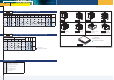
Signals
for Switch Mode Units
The number of options per module may be restricted due to limitation of space inside the module or due to a limited number of
connector pins. Potentiometers or interface cards may be supplied separately for installation outside of the module.
General information
pr input voltage supervision (power ok) incl. relay contacts
A logic signal is given if the input voltage (AC or DC) drops below the specified limit. In
AC input models the rectified input voltage is sensed so that a power fail alarm can be
avoided if at light load mains power returns before the input capacitors are substantially
discharged. A relay contact is provided for failure indication.
dr output voltage supervision (DC ok) incl. relay contacts
A logic signal is given if the output voltage is below the specified limit. A relay contact is
provided for failure indication.
DC ok level: 5V output: 4,75V
all other voltages: 90% of adjusted voltage
cf charger / converter fail supervision incl. relay contacts
A logic signal is given if the input voltage, the auxiliary voltage of the primary side and
the current of the primary side exceed or go below a specified range. A relay contact is
provided for failure indication.
ac AC ok for inverter including relay contacts
A logic signal is given if the output voltage of an inverter is below the specified limit. A
relay contact is provided for failure indication.
IN
L
N
+
-
IN
OUT
IN OUT
IN OUT
primary
control
circuit
supervision
Programming
Converter Programming
programming of output voltage from 0 to 100 %
eu1
eu2
eu3
eu4
by external signal, 0 – 10 V
by external signal, 4 – 20 mA
by 270° potentiometer
by 10 turn potentiometer
programming of output current from 0 to 100 %
ei1
ei2
ei3
ei4
by external signal, 0 – 10 V
by external signal, 4 – 20 mA
by 270° potentiometer
by 10 turn potentiometer
iso isolating amplifier for programming
Programming signal is galvanically isolated from any
potentials of the power supply.
programming via
rs
can
RS232 (external)
CAN Bus (external)
Converter / Charger Monitoring
monitoring of output voltage from 0 to 100 %
mu1
mu2
by external signal, 0 – 10 V
by external signal, 4 – 20 mA
monitoring of output current from 0 to 100 %
mi1
mi2
by external signal, 0 – 10 V
by external signal, 4 – 20 mA
iso isolating amplifier for monitoring
Monitoring signal is galvanically isolated from any
potentials of the power supply.
monitoring via
rs
can
RS232 (external)
CAN Bus (external)
Charger Programming
temperature features
tc
ts1
ts2
temperature compensated charging voltage
(sensor not included)
t
emperature
sensor not interchangeable due to fixed
resistor values
t
emperature
sensor interchangeable, IC controlled
charging characteristics
ch1
ch2
ch3
External card: automatic and manual selection of charging
characteristic (float/ equalized boost charge) with timer
(delayed return to normal operation), including aux.
supply and options “tc” and “ts1”
External card: consisting of option “ch1” plus: Battery
current limitation & battery shunt
External card: consisting of option “ch2” plus: CAN-Bus-
interface & programmable parameters
Monitoring