
Datasheet


DATASHEET
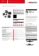
Common-mode Chokes RN series
Current-compensated Chokes
Rated currents from 0.3 to 10 A
DC to 50/60 Hz frequency
100 kHz to 3 MHz common-mode resonance
frequency
Dual-choke configurations
Multiple PCB-mounting options
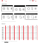
Performance indicators
Technical specifications
Operating voltage
300 VAC
Operating frequency
DC to 50/60 Hz
Rated currents
0.3 to 10 A @ rated ambient temperature
Rated inductance
0.4 to 100 mH
Stray inductance
Typically 1% of L
N
Inductance reduction (DC bias with IN)
Less than 10% (25°C)
High potential test voltage winding-to-
winding @ 25°C
1500 VAC, 2 sec
MTBF @ 40°C/230 V (Mil-HB-217F)
>5,000,000 hours
Surge current @ 10 msec
20 x I
N
@ 25°C
Temperature range (operation and storage)
-40°C to 100°C (40/100/56)
acc. IEC 60068-1
Flammability corresponding to
Potting compound UL94V-0
Housing UL94V-0
Ringcore coating UL94V-0
Design corresponding to
UL 1283, IEC/EN 60938-1
Approvals
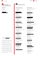
RN chokes are attenuating common-mode or
asymmetric (P/N –> E) interference signals, by being
connected in series with the phase and neutral lines
of an AC powerline input. Symmetrical components
of the noise are also attenuated by the leakage
inductance (stray inductance) of the windings. These
chokes are typically used in conjunction with
suppression capacitors.
Features and benefits
High saturation resistance and excellent thermal
behavior
Through hole pin connections
Dual-choke configuration
Small compact design
Multiple housing options
Custom-specific versions are available on request
Higher temperature versions
Typical applications
Switch-mode power applications
Suppressing common-mode interference levels
EMI input filters
For suppression-equipment with no earth
connection
Phase-angle control circuits in combination with
saturating chokes
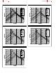
Typical electrical schematic