
User Manual


n Systems for Car Parks and Leisure Centres
ChipCoin Processing Manual
2 Article no. of chapter: 86 93538 (c)
1 Introduction
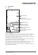
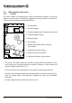
At an entry the coin feeder is located directly in front of the hopper. In case of a
ChipCoin request the coin goes from the hopper to the coin feeder, where it is
guided through the coin channel via stopper and reject magnets and coded and
read by an installed antenna coil.
At an exit the ChipCoin inserted by the customer goes directly into the coin
feeder. Here it is read via the antenna coil and, when found to be valid, is moved
on to the collector receptacle; the gate opens. ChipCoins without exit
authorisation are returned via a reject mechanism to be removed by the customer.
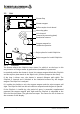
At an automatic pay machine the ChipCoin inserted by the customer likewise
goes directly to the coin feeder. It is read via the antenna coil and "parked" there
as long as necessary until the customer has paid the fee calculated. Simultaneous
to that the insertion aperture of the coin channel (shutter) closes in order to
prevent insertion of coins into the coin feeder.
Due to the different demands (with shutter, without shutter, different coin inlet)
different coin feeders are used for entrance, exit and automatic teller.
All versions are based on identical coin channels (black coin feeder casing)
which are varyingly fitted with magnets, reflex couplers and mechanical
components.
First of all the different versions and their functional operation will be explained.
Maintenance tips will be given on the basis of a fully outfitted coin channel.
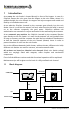
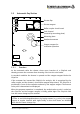
1.1 Block diagram
PIT Basestation
I/O
COM1/EPR
12V
I/Os
I/Os
ChipCoin Interface Hopper
Power supply
Power
Antennas
Coin feeder
Entry only