
Installation Instructions


Installation Instructions
SCR-Smart Card Reader
The content of this document is protected by copyrights.
Date
Name
Created
28..11.11
Hen
File name:
B
--.--.--
-
-
-
Approved
28.11.11
Hen
03 65044 0 B.doc
Index
Date
Created
Approved
Standardization
Standardization
30.11.11
Jor
Scheidt & Bachmann GmbH
D-41238 Mönchengladbach Breite Straße 132
Installation
Instructions SCR
03 65044 0 __
Page: 7 of 8
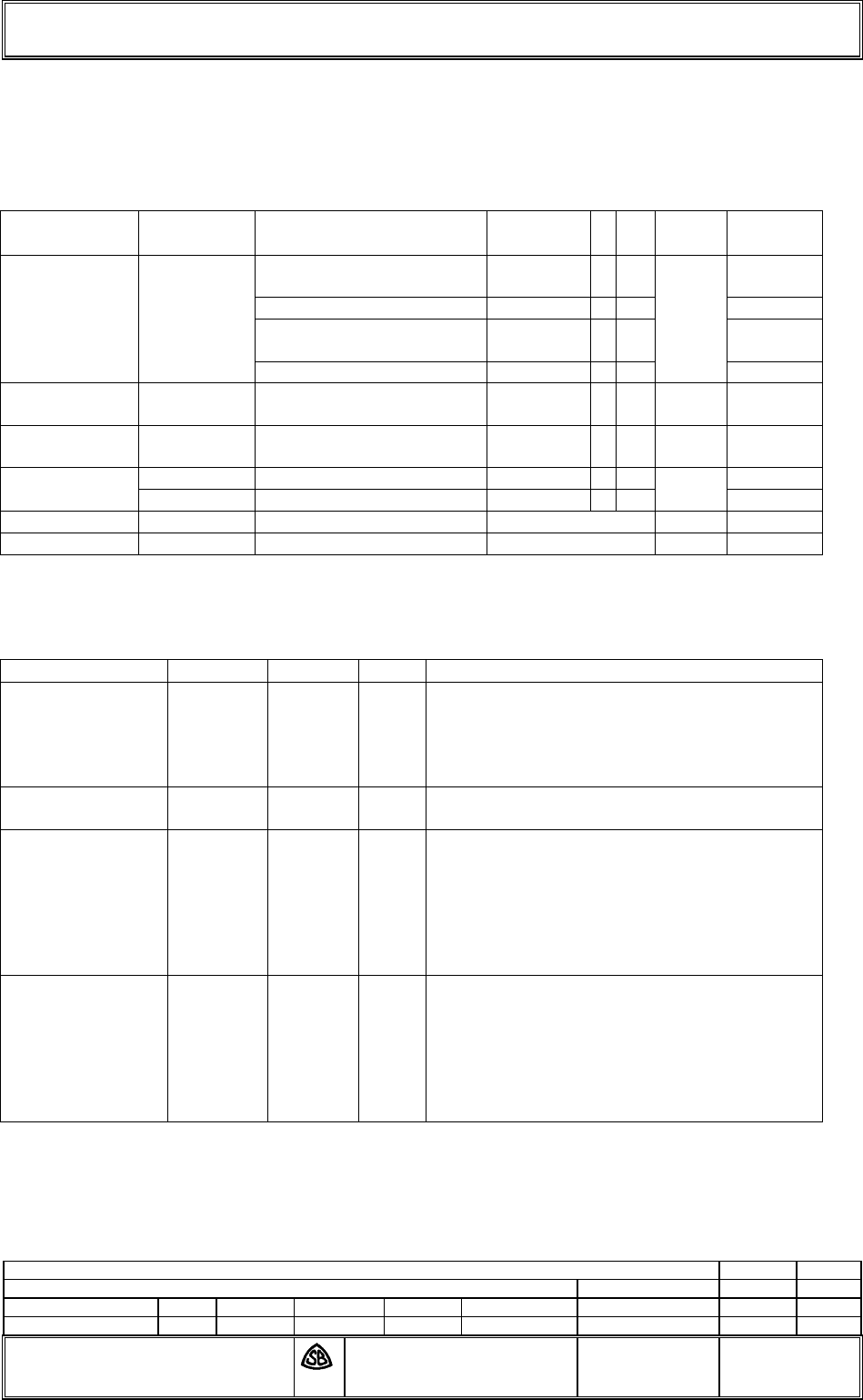
5 List of Cables and components
Cable
Functon
Connector
SCR
Type
No
Count
Length
Power 5V
5V
8V-24V
8V-24V
ST950
2 x AWG20 UL SW
50 62106
0
1
0-3m
3 x AWG20 C UL SW
50 60120
0
A
0-3m
2 x AWG20 UL SW
50 62106
0
0-3m
3 x AWG20 C UL SW
50 60120
0
A
0-3m
LED/Buzzer
ST572 /
ST582
6 x AWG24 C UL SW
50 61441
0
A
2
0-7,3m
Antenna
BU500 /
BU550
M17 / 113-RG316
5063381
0
2
0-7,3m
Host RS232
USB
ST301
4 x AWG24C UL CSA SW
50 61440
0
A
1
0-3m
BU410
0-5
Used components
Component
PCB
Version
Index
Remarks
Reader
Baseboard
03 51634
0
I
The Index shows current design state. Earlier
versions have been part of earlier FCC/IC
certification. Further indices will be covered by
this certification, as long as radio
characteristics will not be affected.
Reader
CPU Module
03 53742
0
I
./.
Antenna Type A
03 57570
./.
./.
To achieve the best performance the
adaptation of the antenna must be changed,
depending on the housing situation (resonance
adaptation).
Scheidt & Bachmann ensures, that resonance
parameters will be met under housing
conditions.
Antenna Type B
03 64127
./.
./.
To achieve the best performance the
adaptation of the antenna must be changed,
depending on the housing situation (resonance
adaptation).
Scheidt & Bachmann ensures, that resonance
parameters will be met under housing
conditions.