
User Manual


Form 51005 Rev. D
12-02-20024
CM5100 COMPUTER MANAGED CYLINDRICAL LOCK
INSTALLATION MANUAL
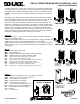
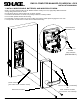
3. CHANGE HAND (IF NECESSARY):
NOTE: The locks are shipped handed as ordered from factory. If it is necessary to change the hand of the lock, follow the
steps below:
A. Remove retractor by loosening two 9/64” socket cap screws which attach it to the outside escutcheon.
B. Remove outside spindle.
C. Loosen 5/32” socket cap screw which secures handle to escutcheon.
D. Remove, rotate and re-install handle (NOTE: some handle designs have an adapter.)
E. Re-install outside spindle, making sure that the round end faces the handle, and the spindle is positioned with its edges
vertical and horizontal as shown in detail below. Note that the cam (inside the escutcheon assembly) must be positioned
such that the dot on it faces the 6 O’Clock position (see detail below).
F. Rotate retractor and re-install it.
G. Change the hand of the handle on the inside escutcheon (not show) the same way. Note that the inside escutcheon has
no retractor.
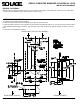
OUTSIDE ESCUTCHEON
OUTSIDE SPINDLE
(ROUND SIDE TOWARD LEVER)
9/64” SOCKET CAP
SCREW
5/32” SOCKET CAP
SCREW
RETRACTOR
OUTSIDE HANDLE
DOT - FACES
DOWN
OUTSIDE
SPINDLE
POSITION
CAM
DETAIL
ADAPTER
LEVER
NOTE:
Some lever designs
require an adapter.