
User manual


Mounting - and Installation Instructions 789-601 / 789-602 incl. Versions /xxx- xxx
WAGO Kontakttechnik GmbH & Co. KG, D-32423 Minden, Hansastraße 27 •www.wago.com 9970-0966/0789-0601/08-07_SW03
3. Restrictions and Regulations
3.1 Legal Regulations
The following topics should be observed:
- the valid laws, norms and regulations
- the applicable local codes in respect to wiring practices
- the state of the technology at time of installation
- the operating manual from sensors and receiver
- the general rules of the technique
- the fact, that instructions manuals could only inform about
general regulations and these have to correspond with plant or
local regulations.
3.1 Restrictions for the Operation of Radio Transmitters or
Receivers
The use of the devices does not need to be registered and is
free in the European Union, Switzerland, Cyprus, the Czech
Republic, Poland and in Slovenia.
The use in other countries requires explicit clarification!
4. Advice for Safety
! Danger for Life existing in case of open
unit by electrical power !
Electrical connection, mounting and dismounting is
only allowed by qualified electrical personal.
Switch Off mains/power connectors before mounting or
dismounting of the Radio Receiver.
Observe assignment of the connectors.
Wrong wiring may destroy the device or lead to short circuits.
Failure to observe these precautions could result in severe
bodily injury or loss of life.
5. Commissioning
Before commissioning the receiver should be proofed for
mechanical- or transport-damages. In case of probable
damages the commissioning of the unit is not allowed.
Read the instruction manual carefully and observe the technical
advices and applying legal regulations.
5.1 Handling Advices / ESD (Electrostatic Discharge)
The modules are equipped with electronic
components that may be destroyed by electrostatic
discharge. When handling the modules, ensure
that the environment (persons, workplace and packing) is well
grounded. Avoid touching of conductive components.
5.2. General Advices for Installation
Avoid installing the module, the antenna and the antenna line
close to sources of transient interferences, such as fluorescent
tubes with defective starter, frequency converters and power
cables. As a result, communication failures may occur leading
to faulty output behavior.
5.3 Advices for Antenna Installation
Use only appropriate antenna (WAGO 758-910 incl. 2.5 m
RG174-cable and SMA-connector; see accessories).
Antenna must be mounted on metal footer with min. dimensions
of 25 cm x 25 cm.
Antenna including cable must have min 30 cm distance to
interference sources and antenna should have free space to
walls of min. 35 cm.
The cable must not be bended because the cable may be
damaged (RG174 bending radius > 15 mm).
5.4 Preconditions for Commissioning
Before commissioning the supply voltage must be applied and
the external antenna must be connected.
Switches (Transmitters) should be „learned“before mounting,
because of reduced transmission range (appr. 5 m) in Learn-
Mode.
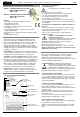
SMA-Antenna-
jack
LED-indication
Supply voltage
Status indication of
outputs 1...4
Learn (LRN)-Button
Clear (CLR)-Button
Terminals for
int. voltage supply
Output Terminals
of relay contacts 789-601
LED-Indicator
Learn-Mode
Mounting and Installation Instructions
789-601 4 Channel Radio Receiver with
Normally Open Contacts;
230V~ / 16A
789-602 4 Channel Radio Receiver with
Change Over Contacts;
230V~ / 8A
Features
•Radio Receiver for Battery and Wireless Sensors
•Status indication via LED
•868 MHz Frequency band
•Transmitter / Receiver assignment via Learn-Mode
•4 potentialfree contacts
•Invertable Outputs; Switch or Toggle beviour selectable
•Supply voltage 24V DC
•External Antenna for optimized Transmission Range (always
required)
•CAGE-CLAMP
®
terminals
1. General Description
The Radio Receivers in the modular installation housing is
designed for switching of 4 individual loads (e.g. lamps) via
radio sensors and push-buttons which are based on Enocean
Radio Technology. Transmission is on a european-wide
harmonized transmission band of 868 MHz. The system is
specially dedicated for flexible, pluggable building or industrial
automation because the expenditure for new or reconfiguring of
installations is minimized.
Compatibility: The Radio Receiver is compatible to wireless
sensors of different manufacturers. The sensors must be based
on EnOcean PTM or STM transmitters (see chapter 8.3).
Transmitter - Receiver - Assignment: One receiver could be
operated from up to 40 transmitters, each channel from up to 10
transmitters. The assignment between sensor and output has to
be teached once during commissioning, the assignments are
stored mains-failure protected in the NV-Ram of the Receiver.
Mixed operation of PTM and STM Modules is possible. One
sensor could be assigned to multiple outputs (1:n); multiple
transmitters could be assigned to one output channel (n:1).
Output Contacts: Loads are operated via 4 relays with
normally-open or change over contacts. The max. permissible
load per contact is either 8A (789-602) or 16A (789-601).
2. Front-View and Operating Elements
Page 1