
Use and Care Guide

5
WALL AND COUNTERTOP PROFILES
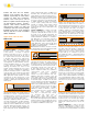
3. Press the perforated anchoring leg of profile
into the mortar and align.
4. Trowel additional thin-set mortar over the
perforated anchoring leg to ensure full
coverage and support of the tile edges.
5. Solidly embed the tiles so that the tiled
surface is flush with the top of the profile;
the profile should not be higher than the tiled
surface, but rather up to approx. 1/32" (1
mm) lower.
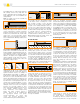
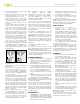
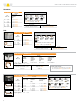
5a. If the FINEC profiles, in aluminum, are
used to create a 3 way external corner, into
which the two upper profiles were fitted
at an angle of 45°, cut the adjoining lower
profile to size. The trapezoid-perforated
anchor ing leg, including the joint spacer,
must be cut off straight to the visible area by
a minimum dimension x, depending on the
profile length; see the AE illustration below.
5b. If the FINEC profiles, in stainless steel,
are used to create a 3 way external corner,
into which the two upper profiles were fitted
at an angle of 45°, cut the adjoining lower
profile to size. In this case, the trapezoid-
perforated anchoring leg must be cut off by
a minimum dimension x, depending on the
profile length, including the visible area has
to be chamfered at a 45° angle; see the E
illustration below.
Note: With FINEC, chamfer tiles adjacent to
the profile by 45°.
RONDEC-DB is intended to be higher than
the tiled surface.
6. Set the tile to the integrated joint spacer,
which ensures a uniform joint of 1/16" -
1/8" (1.5 - 3 mm). With the stainless steel
profiles, DECO-SG, INDEC, and RONDEC-
DB, leave a space of approximately 1/16"
- 1/8" (1.5 - 3 mm).
7. To set tile along the face of RONDEC-CT, apply
thin-set mortar to the back of the tile using a
margin trowel. Press the back-buttered tiles
into the face of the profile, making sure to
force thin-set mortar fully into the dovetailed
grooves. The tiled surface should be flush
with the outer edge of the profile; the profile
should not be higher than the tiled surface,
but rather up to approx. 1/32" (1 mm) lower.
Note: The recessed face accepts tile widths
up to 1-1/8" (29 mm).
8. Fill joints completely with grout or setting
material. Note: Remove the protective foil
from ECK-E immediately after grouting.
9. Work with materials and tools that will
not scratch or damage sensitive surfaces.
Setting materials must be removed
immediately, especially from aluminum.
Note: Matching corners are available
for QUADEC, RONDEC, INDEC,
SCHIENE-STEP (stainless steel version,
depending on vertical leg length), RONDEC-
STEP, and RONDEC-CT. Connectors are
available for QUADEC, RONDEC , and SCHIENE-
STEP (stainless steel version).
Corners and end caps are held in place with
thin-set mortar. Fill the ends of the profile with
thin-set mortar prior to inserting the accessories.
Connectors are held in place with a friction fit.
Insert the connector into the profile approximately
half the length of the connector piece and connect
the adjacent profile.
For installation of SCHIENE-STEP corners and
connectors: Install using KERDI-FIX, silicone, or
similar adhesive. Prior to application, any contact-
inhibiting substances (e.g., grease, etc.) must be
removed. The accessories should overlap the
profiles by at least 3/8” (10 mm). The accessories
must be slid on the profiles during profiles
installation (cannot be placed over the profiles after
installation).
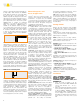
For installation of RONDEC sink corners
(1-1/2" radius):
1. Insert the sink corner connectors into the
profiles. Apply thin-set mortar to the substrate and
firmly embed the profiles into the mortar.
2. Using a margin trowel, fill the back of the sink
corners with thin-set mortar. Install the corners
over the connectors and align. Setting materials
must be removed immediately.
QUADEC-K/DIADEC-K
1. QUADEC-K may be used to cover assembly
edges up to 1/2" (12.5 mm) thick. DIADEC-K
may be used to cover assembly edges at least
1/4" (6 mm) thick.
2. Fill the profile cavity with thin-set mortar.
3. Using a notched trowel, apply thin-set mortar
to the area where the profile is to be placed.
4. Press the profile into the mortar and align.
Leave a space of approximately 1/16"-1/8"
(1.5 – 3 mm) between the profile and tile.
5. Fill joints completely with grout or setting
material.
6. Work with materials and tools that will not
scratch or damage sensitive surfaces. Setting
materials must be removed immediately.
Note: QUADEC-K may also be adhered using
KERDI-FIX. Matching inside/outside corners and
connectors are available.
Corners/end caps are held in place with thin-set
mortar. Fill the ends of the profile with thin-
set mortar prior to inserting the accessories.
Connectors are held in place with a friction fit.
Insert the connector into the profile approximately
half the length of the connector piece and connect
the adjacent profile.
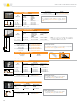
DESIGNBASE-SL
1. DESIGNBASE-SL is applied to prepared walls
using KERDI-FIX or other suitable adhesive.
Prior to applying the adhesive, make sure that
all surfaces are free from adhesion-inhibiting
substances such as oil or grease.
2. Apply beads of adhesive to the back of the
profile and press the profile onto the wall,
ensuring solid contact throughout.
3. Use a suitable cleaning agent to remove any
excess adhesive from around the profile.
Remove the protective foil.
Note: The accessories must be slid on the profiles
during installation (cannot be placed over the
profiles after installation). The optional sealing lip is
inserted into the profile prior to installation.
ECK-K/-KHK/-KI
1. ECK-K/-KHK/-KI are applied to
prepared wall corners using
KERDI-FIX, silicone, or a similar adhesive.
Prior to applying the adhesive, make sure that
all surfaces are free from adhesion-inhibiting
substances such as oil or grease. Apply a
bead of adhesive to the back of each of the
profile legs; then press the legs onto the wall
covering, ensuring that the lateral edges lie flat
and have solid contact throughout.
2. Use a suitable cleaning agent to remove any
excess adhesive from around the profile legs.
3. Remove the protective foil.
Install ECK-KHK inside and outside corners using
a permanently elastic, waterproof adhesive (e.g.,
KERDI-FIX or silicone). Prior to application, any
contact-inhibiting substances (e.g., grease, etc.)
must be removed. The connectors should overlap
the profiles by at least 3/8" (10 mm).
QUADEC-FS
1. Set tiles up to the area where QUADEC-FS is
to be installed as a feature strip.
2. Using a notched trowel, apply a sufficient
amount of thin-set mortar to this area and/
or to the back of QUADEC-FS and press
the profile into the mortar and align. Leave
a space of approximately 1/16" – 1/8"
(1.5 – 3 mm) between the profile and the tile.
Note: QUADEC-FS may also be attached to
the substrate with fasteners.
3. Set the adjacent row of tiles. Leave a space
of approximately 1/16" – 1/8" (1.5 – 3 mm)
between the profile and the tile.
4. To set tile along the face of QUADEC-FS, apply
thin-set mortar to the back of the tile using a
margin trowel. Press the back-buttered tiles
into the face of the profile, making sure to
force thin-set mortar fully into the dovetailed
grooves. The tiled surface should be flush
with the outer edge of the profile. Note: The
recessed face accepts tile widths up to 2" (51
mm).
5. Fill joints completely with grout or setting
material.
6. Work with materials and tools that will not
scratch or damage sensitive surfaces. Setting
materials must be removed immediately.
Note: Matching inside corners/outside corners/
end caps are available.
Corners/end caps are held in place with thin-set
mortar. Fill the ends of the profile with thin-set
mortar prior to inserting the accessories.
AE
=X
E
=X 45°