
Use and Care Manual

6
MOVEMENT JOINTS AND COVE-SHAPED PROFILES
6
Regardless of the cutting tool used, remove
any burrs from the cut end of the profile with
a file or similar before installation.
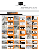
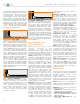
Stainless steel profiles may be cut using any
of the following options:
• Variable-Speed Angle Grinder set to the
lowest speed using the Schluter
®
-PROCUT-
TSM cutting wheel.
• Band Saw with a metal cutting blade.
Regardless of the cutting tool used, remove
any burrs from the cut end of the profile with
a file or similar before installation.
Installation
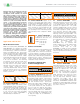
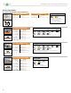
Mortar Bed Joint Profiles
MOP, and MP/MPV
1. Select profile height according to the
height of the assembly.
Note: for DILEX-MP, attach necessary
snap-on extensions (-MPV).
2. Set the profile flush against the edge
area of an already completed field.
The profile must be completely embedded
laterally.
3. Install tiles for the adjacent field flush to
the profile surface. The profile must be
completely embedded laterally.
4. Fill the remaining joint between the profile
and the covering completely with grout or
setting material.
Installation note on joint repair:
Prepare the joint’s width and depth
appropriately and insert profile into joint.
Fill joint space between profile and
covering completely with grout, epoxy, or
thin-set mortar.
DFP
1. Install DILEX-DFP between BEKOTEC
panels at door areas, for dividing screed
surfaces and where the covering meets
walls or restraining surfaces as desired.
Note: The separation of screed surfaces
using DILEX-DFP can prevent sound bridges.
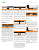
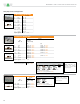
Surface Joint Profiles
EZ
1. Select DILEX-EZ 6 or DILEX-EZ 9
according to tile thickness. For tile
thicknesses greater than 11/32"
(9 mm), DILEX-EZ 9 must be back-
buttered with thin-set mortar.
2. Set tiles up to the point where
DILEX-EZ is to be installed. Apply
thin-set mortar to tile edges.
The profile must align directly with
movement joints in the substrate below.
Press the profile against the tile edge
and flush with the tile surface so that
the ribbed, hourglass-shaped section is
completely embedded in the mortar.
3. For the next row of tiles, apply thin-set
mortar to the side wall of the DILEX-EZ
profile already in place; then press the
tiles against the profile so that they are
flush with the profile surface.
4. DILEX-EZ may be installed with or without
a small joint to the adjacent tile.
BWS, BWB, EDP, KSN, and AKWS
1. Select profile according to tile thickness
and format.
2. Using a notched trowel, apply thin-set
mortar over the area where the profile is to
be placed. The profile must align directly
with movement joints in the substrate
below.
3. Press the perforated anchoring legs of the
profile into the mortar and align.
4. Trowel additional thin-set mortar
over the perforated anchoring legs to
ensure full coverage and support of
the tile edges.
5. Solidly embed the tiles so that the tiled
surface is flush with the top of the profile;
the profile should not be higher than the
tiled surface, but rather up to approx.
1/32" (1 mm) lower.
6. A joint of approximately 1/16" - 1/8"
(1.5 - 3 mm) should be left between the
tile and the profile.
7. Fill the joint completely with grout or
setting material.
EKSB
1. Select Schluter
®
-DILEX-EKSB according
to the floor covering thickness.
2. Apply a suitable adhesive over the
area where the profile is to be placed.
The adhesive must secure the profile
and prevent the anchoring legs from
telegraphing through the floor covering.
Suitability of the adhesive may depend
on the particular floor covering used;
consult Schluter
®
-Systems for more
information. The profile must align directly
with movement joints in the substrate
below.
3. Press the perforated anchoring legs of the
DILEX-EKSB into the adhesive and align.
Clean or degrease the anchoring legs as
required.
4. Install floor covering material per
manufacturer’s instructions so that the
surface is flush with the top of the profile;
the profile must not be higher than the
surface, but rather up to approx. 1/32" (1
mm) lower.
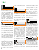
Expansion Joint Profiles
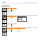
BT/BTO/BTS
1. Select profile according to tile thickness
and format.
2. Using a notched trowel, apply thin-set
mortar over the area where the profile is to
be placed. The profile must align directly
with movement joints in the substrate
below.
3. Press the perforated anchoring legs of
the profile into the mortar and align.
4. Trowel additional thin-set mortar over
the perforated anchoring legs to ensure
full coverage and support of the tile
edges.
5. Solidly embed the tiles so that the
tiled surface is flush with the top of the
profile; the profile should not be higher
than the tiled surface, but rather up to
approx. 1/32" (1 mm) lower.
6. For DILEX-BT, the tile is set to the
integrated joint spacer, which ensures a
uniform joint of 1/16" - 1/8" (1.5 - 3 mm).
7. Fill the joint completely with grout or
setting material; remove the protective
foil from DILEX-BT.
8. For DILEX-BTO the installation of the
profile on the wall and ceiling surfaces
is essentially equivalent to floor
applications.
9. DILEX-BTS can be inserted into existing
joint spaces. The joints must be at least
1-3/4" (44 mm) wide and 3/8" (10 mm)
deep. The lateral anchoring legs are
adhered to the existing covering with a
suitable adhesive (e.g., epoxy resin) or
mechanically fastened to the covering
with the appropriate screws.
Perimeter Joint Profiles
AS
1. Thoroughly clean the contact area on
adjoining fixtures where DILEX-AS will
be positioned.
2. Using a notched trowel, apply the
thin-set mortar over the area where the
trapezoid-perforated anchoring leg will
be placed.
3. Remove the paper from the self-
adhesive tape. Apply Schluter
®
-
KERDI-FIX or silicone sealant parallel
and adjacent to self-adhesive tape.
Press the profile with self-adhesive
tape against the fixture in such a way
that the perforated anchoring leg
can also be pressed into the applied
thin-set mortar.
4. Install inside corners and end caps with
KERDI-FIX or silicone prior to setting
tiles.
5. Trowel additional thin-set mortar over
the perforated anchoring leg to ensure
full coverage.
6. A joint of approx. 1/16" - 1/8" (1.5 -
3 mm) should be left between the tile
and the profile.
7. Fill the joint completely with grout or
setting material.