
Use and Care Manual
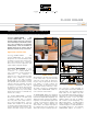

FLOOR DRAINS
4
Note: When using the stainless steel
bonding flange, the KERDI is bonded
to the integrated bonding flange with
KERDI-FIX adhesive/sealant. The
stainless steel bonding flange must
be clean and free of grease or other
contaminants prior to KERDI-FIX
application.
3. Embed a 20" x 20" (50 x 50 cm) cut
section of KERDI in the bond coat and
work the membrane onto the KERDI-
DRAIN bonding flange and surrounding
membrane to ensure full coverage
and remove air pockets. The KERDI is
carried to the step in the bonding flange
(template provided) and must overlap
the DITRA or DITRA-XL membrane by
a minimum of 2" (50 mm).
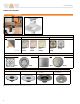
Grate assembly
Grate
1. The grate assembly is installed in
conjunction with the tile. Place the
height adjustment collar inside the
lateral adjustment ring and snap the
grate into place.
Note: For drains with 6" (150 mm)
grates, the height adjustment collar
is integrated with the grate. For the
residential adaptor kit, there is no lateral
adjustment ring.
2. Fill the step in the bonding flange
with unmodified thin-set mortar and
back-butter the underside of the
grate to ensure full support. Press the
assembly into the mortar and install
the surrounding tiles, ensuring full
coverage.
3. Position the grate to match the joint
pattern of the tile covering and press
flush with the tile surface. Remove all
excess setting material.
Note: Protect the visible surface of the
grate from contact with setting and grouting
materials. In particular, anodized aluminum
is sensitive to alkaline materials.
Tileable Covering Support
1. The covering support is installed in
conjunction with the tile. Place the tile
spacer inside the lateral adjustment
ring.
2. Fill the step in the bonding flange with
thin-set mortar and press the assembly
into the mortar. Install the surrounding
tiles up to the tile spacer using
unmodified thin-set mortar, ensuring full
coverage. Set the tile to the integrated
tabs on the lateral adjustment ring,
which provide for a flush transition
to the covering support. Remove all
excess setting material. Position the tile
spacer to match the joint pattern of the
tile covering.
3. Apply tile to the top of the covering
support using unmodified thin-set
mortar. The tile is installed flush with all
sides of the covering support to provide
the drainage openings.
4. Once the assembly has been set
and grouted, remove the tile spacer
and insert the tiled covering support
in the lateral adjustment ring.
Note: For acid-resistant coverings,
use an epoxy adhesive to set and grout
the tile.
KERDI-LINE
Preparation
1. Any leveling of the floor must be done
prior to the installation of the channel
body. For installation adjacent to the
wall, the channel body must be aligned
in accordance with the thickness of
the wall covering. For intermediate
installation, use the supplied filling strip
with peel-and-stick adhesive layer to
make the channel support symmetrical.
2. KERDI-LINE can be installed in
conjunction with the provided
channel support as described below
or set in loose mortar. KERDI-LINE
is connected to the waste line with
the appropriate mechanical no-hub
coupling in accordance with the
coupling manufacturer’s instructions.
Channel body installation
Access to plumbing from below
When there is access to the plumbing
from below and the waste line can be
connected after installing KERDI-LINE, the
channel body may be set without making a
connection to the waste line simultaneously.
1. Apply unmodified thin-set mortar to
the substrate where the drain is to
be placed with a notched trowel and
solidly embed the channel support in
the mortar.
2. Apply unmodified thin-set mortar to
the top of the channel support with a
notched trowel and press the channel
body firmly into the mortar, ensuring full
support of the bonding flange. Check
to make sure the KERDI-LINE is level.
No access to plumbing from below
When there is no access to the plumbing
from below, the channel body must be
set and connected to the waste line
simultaneously.
1. Begin the drain installation by dry fitting
the components. Measure and cut a
section of pipe to connect the coupling
to the odor trap below the floor, using
the channel support as a spacer.
2. Apply unmodified thin-set mortar to
the top of the channel support with a
notched trowel and press the channel
support firmly onto the underside of the
channel body. Attach the mechanical
coupling to the drain outlet and the cut
section of the pipe per the coupling
manufacturer’s instructions.
3. Apply unmodified thin-set mortar to
the substrate where the drain is to
be placed with a notched trowel.
Prepare the cut section of pipe and
odor trap with cleaner, primer and ABS
or PVC cement per the solvent cement
manufacturer’s instructions.
4. Solidly embed the channel support and
KERDI-LINE into the mortar on the floor
and connect the cut section of pipe to
the odor trap. Check to make sure the
KERDI-LINE is level.
5. The screed is then placed flush with the
top of the bonding flange of the KERDI-
LINE. Slope the mortar bed using the
bonding flange and mortar screeds as
guides.
Note: KERDI-FIX or other adhesives that
are compatible with EPS foam can be used
to install the channel support and channel
body as an alternative to thin-set mortar.
Apply a generous bead of KERDI-FIX to
the top and bottom of the channel support.
The use of KERDI-FIX limits the ability to
level KERDI-LINE.
Note: Schluter
®
-Systems recommends a
leak test be performed on the connection
between the drain and the waste line prior
to continuing with the remainder of the
installation whenever possible.
Connection to waterproofing
membranes
The KERDI or DITRA waterproofing
membranes can be installed as soon as the
mortar bed can be walked upon.
1. KERDI, DITRA or DITRA-XL is installed
up to the outer edge of the KERDI-LINE
bonding flange using unmodified thin-
set mortar. The thin-set mortar must be
mixed to a fairly fluid consistency, but