WATSON 5 LTU / NTU Operating Manual Document Identification SZ-DOC-W5-1.doc Document Version 1.5 Document Revision 2002-10-15 Schmid Telecom AG Tel.: +41 1 456 11 11 Binzstrasse 35 Fax: +41 1 466 92 92 CH-8045 Zurich Switzerland www.schmid-telecom.
SZ-DOC-W5-1.pdf Version: 1.5 LTU/NTU Operating Manual Version Control Version of Operating Manual Major changes to previous version 1.0 Initial version, LSs 1.1 Added description for “Remote Firmware Download Procedure” Added new Monitor commands STARTBER,STOPBER, READBER, RESETBER 1.2 Description for ALARM HISTORY, POWER BACKOFF and CLOCK POLARITY commands added, URr 1.3 New commands added according to Firmware Version 1.4, TS, DIAGNOSTIC, etc, GWp 1.
LTU/NTU Operating Manual SZ-DOC-W5-1.pdf Version: 1.5 Declaration of Conformity Watson 5 Tabletop W5 NTU E1/PRA/120Ohm, single link 1p SZ.886.V310 W5 NTU E1/120Ohm & nx64, single link 1p W5 NTU E1/PRA/75Ohm, single link 1p SZ.886.V318 SZ.886.V330 W5 NTU E1/75Ohm & nx64, single link 1p SZ.886.V338 W5 NTU nx64, single link 1p SZ.886.V380 W5 NTU E1/PRA/120Ohm, single link 2p SZ.886.V410 W5 NTU E1/PRA/120Ohm & nx64, single link 2p SZ.886.V418 W5 NTU E1/PRA/75Ohm, single link 2p SZ.886.
SZ-DOC-W5-1.pdf Version: 1.5 LTU/NTU Operating Manual 99/5/EEC Directive containing requirements in respect with Radio & Telecommunication Terminal Equipment.
LTU/NTU Operating Manual SZ-DOC-W5-1.pdf Version: 1.5 Contents 1 2 The Watson 5 Family ...............................................................................................................................1 1.1 Important Safeguards ......................................................................................................2 1.2 Ordering Information........................................................................................................4 1.2.1 LTU ...................
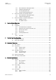
SZ-DOC-W5-1.pdf Version: 1.5 LTU/NTU Operating Manual 3.4.8 3.4.9 3.4.10 3.4.11 4 5 6 7 vii Clock Polarity ...............................................................................................22 Byte Timing..................................................................................................22 Multiservice / nx64 Clock Modes ......................................................................22 Clock Direction...................................................................
LTU/NTU Operating Manual SZ-DOC-W5-1.pdf Version: 1.5 7.3.3 7.3.4 7.3.5 7.3.6 8 9 10 11 Fault and Maintenance Management FMM..........................................................50 Configuration Management CM ........................................................................58 Accounting Management AM ...........................................................................68 Security and Remote Management SM ..............................................................68 7.
SZ-DOC-W5-1.pdf Version: 1.5 LTU/NTU Operating Manual 11.3.3 11.4 12 13 14 EMC..........................................................................................................108 Physical Dimensions....................................................................................................108 11.4.1 LTU ..........................................................................................................108 11.4.2 NTU ..............................................................
LTU/NTU Operating Manual SZ-DOC-W5-1.pdf Version: 1.5 Figure 10-1: DSL Connector Backview ........................................................................................91 Figure 10-2: Front-view nx64 Sub-D25 connector .........................................................................94 Figure 13-1: Standard Test Loops ............................................................................................114 Tables Table 1-1: Ordering Numbers for Watson 5 LTU .........................
SZ-DOC-W5-1.pdf Version: 1.5 LTU/NTU Operating Manual 1 The Watson 5 Family The Watson 5 family is a SHDSL/SDSL transmission system compliant to: • ITU-T G.991.2 Annex B (G.shdsl) and • ETSI TS 101 524 (ETSI SDSL). It is based on a Trellis-coded PAM16 linecode supporting multiple linerates as well as 1 pair, 2 pair, and 4p DSL transmission. It was designed with flexibility and modularity in mind.
LTU/NTU Operating Manual SZ-DOC-W5-1.pdf Version: 1.5 1.1 Important Safeguards This section describes the safety precautions the user should abide by when operating this equipment. • Transport this equipment in its original packaging or by using appropriate materials to prevent against shock and impact. • Before setting up this product for operation please make note of the accompanying environmental requirements. • Slots and openings in the unit are provided for ventilation.
SZ-DOC-W5-1.pdf Version: 1.5 LTU/NTU Operating Manual Information for the Technician • Remove the network and power supply cables before opening this equipment or removing the plug-in units, respectively. Safety Notices Do not proceed any of these notices until you have fully understood the implications: 3 • Caution! Potential hazard that can damage the product. • Important! Potential hazard that can seriously impair operation.
LTU/NTU Operating Manual SZ-DOC-W5-1.pdf Version: 1.5 1.2 Ordering Information 1.2.1 LTU Description W5 LTU W5 LTU W5 LTU W5 LTU W5 LTU W5 LTU W5 LTU W5 LTU W5 LTU W5 LTU E1/120Ohm & nx64, single link 1p E1/75Ohm & nx64, single link 1p E1/120Ohm & nx64, single link 2p E1/75Ohm & nx64, single link 2p 2*E1/120Ohm, dual link 1p 2*E1/75Ohm, dual link 1p 2*nx64, dual link 1p 2*E1/120Ohm, dual link 2p 2*E1/75Ohm, dual link 2p 2*nx64, dual link 2p Product Number Plug-in SZ.866.V318Wxx SZ.866.V338Wxx SZ.866.
SZ-DOC-W5-1.pdf Version: 1.5 LTU/NTU Operating Manual 1.2.3 Accessories Subrack ACU2R ACU48R Nx64kbit/s Cables SZ.379.V3W SZ.369.V5W SZ.369.V4F V.35 DTE, 3m length V.35 DCE, 3m length V.36 DTE, 3m length V.36 DCE, 3m length X.21 DTE, 3m length X.21 DCE, 3m length AC/DC Adapter, 230V version AC/DC Adapter 230V, 15W AC/DC Adapter, 115V version DC/DC Adapter, 48/60V 19” Minirack Mechanics LTU 19” Minirack Mechanics NTU SZ.378.0F1.V1 SZ.378.0G1.V1 SZ.378.0H1.V1 SZ.378.0J1.V1 SZ.378.0K1.V1 SZ.378.0L1.V1 SZ.
SZ-DOC-W5-1.pdf Version: 1.5 LTU/NTU Operating Manual 2 Installation Guide This chapter gives a brief overview over the necessary steps to install a Watson modem. 2.
LTU/NTU Operating Manual SZ-DOC-W5-1.pdf Version: 1.5 2.3 Installing a Watson Modem Caution: Important: • Unpack and mount the unit safely. Keep chapter "Important Safeguards" in mind when choosing an appropriate place for tabletops. Miniracks can be mounted in 19" racks. • Plug-in units are simply inserted into subracks and will start operation immediately. Mounting of subracks is described in manual "Installation Manual of Subrack". • Check the setting of the remote power switch/jumper.
SZ-DOC-W5-1.pdf Version: 1.5 LTU/NTU Operating Manual 3 Interface Configuration Options The following sections describe the various configuration options. On the plug-in LTU, the operating modes are configurable via the V.24 monitor interface or via the TMN interface of the ACU, whereas on the minirack LTU, table-top NTU and minirack NTU, they are directly configurable via the monitor interface. If the LTU/NTU is slave, it is also configurable from the master side.
LTU/NTU Operating Manual SZ-DOC-W5-1.pdf Version: 1.5 3.1.2 Line Rate According to ETSI TS 101 524 Watson 5 supports payload bit rates on multiples of 64 kbit/s with the optional use of Z-bits. Payload Block Bit Rate = N ∗ 64 kbit/s + i ∗ 8 kbit/s with 3 ≤ N ≤ 36 and i = 0, 1 Watson 5 offers the option of configuring one Z-bit as a supplementary bandwidth enhancement to the embedded operating channel (EOC) within the SHDSL overhead. The effective bandwith of the eoc without Z-bits is 3.
SZ-DOC-W5-1.pdf Version: 1.5 LTU/NTU Operating Manual 3.1.3 Power Back-off In order to reduce ingress on other transmission systems operating on adjacent pairs bundled in the same cable, the transmit power of LTU and NTU can be decreased by activating the power back-off mode. 3.1.4 Symmetric and Asymmetric PSD Mask For payload bit rates of 2048 kbit/s and 2304 kbit/s the Power Spectral Density (PSD) masks of LTU and NTU can be switched into symmetric or asymmetric mode.
LTU/NTU Operating Manual SZ-DOC-W5-1.pdf Version: 1.5 3.2.1.2.2 E-bit Insertion • If automatic E-Bit generation is enabled, detected CRC4 errors will cause the assertion of the E-bits. • If disabled, all E-Bits are set to ‘1’. 3.2.2 AIS Generation If this option is enabled, an unframed AIS (all ones) will be transmitted on the E1 side, irrespective of whether the system is configured in transparent or framed mode.
SZ-DOC-W5-1.pdf Version: 1.5 LTU/NTU Operating Manual INP 2048 kHz E1 Side DSL Side External clock E1 Tx 2 Mbit/s Tx Clock Stuff/ Delete Internal Clock E1 Rx Recovered 2048 kHz Clock 2048 kHz ClockRecovery DSL Tx DSL Rx Figure 3-1: Clock Sources Note: Signals towards the transceiver section are denoted as Tx and signals coming from the transceiver sections are denoted as Rx. As long as the DSL link is not established, the internal clock oscillator is used as clock source.
LTU/NTU Operating Manual SZ-DOC-W5-1.pdf Version: 1.5 3.2.4.2 External Clock Mode Tx 2 Mbit/s Rx DSL NTU/ LTU LTU Rx 2 Mbit/s Tx INP 2048 kHz Figure 3-3: External Clock Mode In “External Clock” mode, the 2048kHz input clock is fed directly in the LTU in case of the minirack or via the ACU clock input in case of the plug-in LTU. The external clock is used as the E1 reference clock. If the “External Clock” option is enabled, the primary E1 clock source is the external clock.
SZ-DOC-W5-1.pdf Version: 1.5 LTU/NTU Operating Manual T V3 V3' DSL Link NT2/TE NT1 LT DSL XVR DSL XVR ET Figure 3-4: Reference Points of the PRA Normally, the PRA-digital section (NT1 and LT) is configured as a digital link with CRC processing in the NT1 (option 2, according to I.604). However, also the other subscriber access options described in I.604 Annex A, can be configured. One of the DSL system units must be configured as master and the other as slave.
LTU/NTU Operating Manual SZ-DOC-W5-1.pdf Version: 1.5 The detection of events and the state information are still valid as in normal PRA operation mode (option 2). Depending on the distribution of NT1 and LT functionality, two set-ups are possible for option 1: • The master is E1 configured transparent, AIS-generation on and AIS-detection off; the slave is PRA NT1 & LT, CRC4 processing off. • The master is PRA LT with CRC4 processing off; the slave is PRA NT1 with CRC4 processing off.
SZ-DOC-W5-1.pdf Version: 1.5 LTU/NTU Operating Manual NT2 R RX M L LT NT1 TX G R L G M L ET M G G M R L R Digital Link T L R M G Local CRC error information Remote CRC error information CRC Monitor CRC Generator V3' Mandatory Optional Figure 3-6: Digital Link with CRC Processing in the NT1 CRC4 is generated towards the NT2/TE and towards the ET and monitored at both sides of the NT1.
LTU/NTU Operating Manual SZ-DOC-W5-1.pdf Version: 1.5 NT2 R RX M L TX G NT1 LT R L R L G M L M G G M R L ET M G G M R L R Digital Link T L R M G Local CRC error information Remote CRC error information CRC Monitor CRC Generator V3' Mandatory Optional Figure 3-7: Digital Link with CRC Processing in the LT and NT1 3.3.2.4 Digital Link with CRC Monitoring in the NT1 (Option 4) CRC4 multiframe alignment and checksum words are not regenerated in both directions, i.e.
SZ-DOC-W5-1.pdf Version: 1.
LTU/NTU Operating Manual SZ-DOC-W5-1.pdf Version: 1.5 3.4 nx64 kbit/s Interface This chapter describes the configuration options and alarms related to the nx64 kbit/s user interface. 3.4.1 Features • The nx64 kbit/s interface is software-configurable between V.35, V.36 and X.21. • The bit rate can be selected in steps of 64kbit/s from 64kbit/s (n=1) up to 2304kbit/s (n=36, Dual LTU) and 4608 kbit/s (n=72, NTU). • Independent receiving and transmitting clocks for V.35 and V.36.
SZ-DOC-W5-1.pdf Version: 1.5 LTU/NTU Operating Manual 3.4.5 Handshake Operation When no loopback is established, the control circuits perform this handshake protocol: • 105 (RTS Request to send; X.21: C): Input from DTE. For X.21, C = OFF will cause a DTR alarm. • 106 (CTS Ready for sending, X.21: I): - if Handshake option enabled: is set ON when a DSL connection is established and 105 = ON is detected.
LTU/NTU Operating Manual SZ-DOC-W5-1.pdf Version: 1.5 3.4.8 Clock Polarity In X.21 mode the sampling instant for the incoming data stream on circuit T of the user interface (UIF) can be switched to rising or falling slope of the contradirectional clock circuit S. Data transitions of the received data on UIF circuit R is not influenced by this setting. In default configuration "normal" circuit T is sampled on rising edge of clock S.
SZ-DOC-W5-1.pdf Version: 1.5 LTU/NTU Operating Manual • Remote: The transmitting clock is the recovered remote clock, i.e. the same clock as the receiving clock (115) at the V.35 and V.36 interface (contra-directional, circuit 114). The clock mode to be used depends on the individual network configuration: • nx64 kbit/s - nx64 kbit/s connection: First, it should be checked whether the equipment connected to the nx64 port uses a transmitting clock output or input.
LTU/NTU Operating Manual SZ-DOC-W5-1.pdf Version: 1.5 Figure 3-9: Time Slot Mapping: 16 frE1 Time Slots to E1 3.5.2 nx64 kbit/s to nx64 kbit/s Time Slot Mapping DSL Payload Sub-Block B1 B2 B3 B4 … . B16 B17 B18 … . nx64 Time Slots at User Interface, Master Side N1 N2 N3 N4 … . N16 N17 N18 … . Bn nx64 Time Slots at User Interface 1, Slave Side N36 N1 N2 N3 N4 … . N16 N17 N18 … . N36 Figure 3-10: Time Slot Mapping: 16 nx64 Time Slots to nx64 3.5.
SZ-DOC-W5-1.pdf Version: 1.5 LTU/NTU Operating Manual 3.5.4 E1 to E1 & nx64 kbit/s Multiservice Time Slot Mapping When both E1 and nx64 kbit/s interface are equipped, they can be used concurrently. The available DSL bandwidth is then shared between the m time slots of the E1 interface and the n time slots of the nx64 kbit/s interface. DSL Payload Sub-Block B1 B2 B3 B4 … . B16 B17 B18 … .
LTU/NTU Operating Manual SZ-DOC-W5-1.pdf Version: 1.
SZ-DOC-W5-1.pdf Version: 1.5 LTU/NTU Operating Manual Tx A TMN Interface Tx B CMU MR Rx A Rx B X.25 or LAN Tx A Tx B Rx A Rx B LTU MR Management Center Tx A Tx B LTU MR Rx A Rx B Tx A … LTU MR Figure 3-13: TMN Bus 4-Wire Connection for Minirack Units 3.6.2 TIA/EIA-485 2-wire Bus TMN communication can be established via an EIA-485 2-wire connection as well. In this case no crossing of signals between CMU and LTU is required. X.
LTU/NTU Operating Manual SZ-DOC-W5-1.pdf Version: 1.5 Management Center X.
SZ-DOC-W5-1.pdf Version: 1.5 LTU/NTU Operating Manual Plug-in versions of ACU and CMU offer jumpers to connect a simple 120 Ω parallel termination to both differential wire pairs of the TMN bus. ACU Plug-in: Closing J4 and J5 will activate the termination. CMU Plug-in: Closing jumper ST4 and ST5 will activate the termination.
SZ-DOC-W5-1.pdf Version: 1.5 LTU/NTU Operating Manual 4 Performance Monitoring The transmission performance of a DSL link can be monitored in two different ways. The DSL signal quality is typically used during installation and maintenance procedures, whereas the G.826 error performance parameters are intended to be used for long term evaluation of an operating DSL link. Refer also to the “SQ” and “G826” monitor commands described in the “Monitor Operation” chapter. 4.
LTU/NTU Operating Manual SZ-DOC-W5-1.pdf Version: 1.5 4.2.2 E1 Interface Slave Master CRC4 CRC6 CRC6 CRC4 RX TX Test E1 Test Gen. CRC4/E-bit G.826 Evaluation Gen. DSL CRC6 CRC6 Gen. G.826 Evaluation Gen. Test CRC4/E-bit E1 Test TX RX Slave TX E1 CRC4_T CRC6 Test Gen. CRC4/E-Bit RX Master G.826 Evaluation Gen. CRC6 Test CRC6 RX Test DSL Channels A & B CRC6 G.826 Evaluation Gen. E1 TX Figure 4-1: E1 G.
SZ-DOC-W5-1.pdf Version: 1.5 LTU/NTU Operating Manual 4.2.3 ISDN PRA Interface Slave (NTU-PRA) CRC4_V3 CRC4_T TX TE Test CRC4/E-Bit RX Gen. Master (LTU or NTU-E1 transp.) Gen. G.826 Evaluation CRC6 Test RX Test Gen. CRC4/E-Bit Test CRC6 CRC6 DSL Channels A & B CRC6 Gen. G.826 Evaluation ET TX Figure 4-2: PRA G.
SZ-DOC-W5-1.pdf Version: 1.5 LTU/NTU Operating Manual 5 Alarms 5.1 LEDs The two LEDs ′Status Local′ and ′Status Remote′ are used to display normal operation condition and alarm condition. Each LED can be green, amber, or red according to the following table. On the Dual LTU, the LEDs are numbered from 1 to 4 and have the following functions: LED Number System Local / Remote 1 2 3 4 1 1 2 2 Local Remote Local Remote Table 5-1: LED indication 5.1.
LTU/NTU Operating Manual SZ-DOC-W5-1.pdf Version: 1.
SZ-DOC-W5-1.pdf Version: 1.5 LTU/NTU Operating Manual • Receiving AIS at the V3 reference point (AIS-V3) nx64 kbit/s Interface: • Loss of codirectional clock or clock rate mismatch (clock mode: nx64 Port) on the nx64 kbit/s side (LOC), • Data Terminal Ready (DTR, circuit 108/2) on the nx64 Port is detected as 'OFF'. For X.21, the control-signal (C) is represented by DTR.
LTU/NTU Operating Manual SZ-DOC-W5-1.pdf Version: 1.5 Non-urgent Alarm: • At least one of the LTU – LEDs displays an amber alarm and none of the LTU – LEDs displays a red alarm • Power failure of any one of the LTUs • Power failure of the auxiliary +5VDC auxiliary supply on the ACU • Power failure of one of the –48 VDC supplies 5.2.2 NTU The two alarm relays “Urgent” and “Non-urgent” are located on the NTU, the alarm contacts are available on the monitor connector. 5.2.2.
SZ-DOC-W5-1.pdf Version: 1.5 LTU/NTU Operating Manual 6 Power Concept 6.1 LTU 6.1.1 Power and Grounding Each plug-in LTU is fed via subrack backplane with (dual) -48VDC (referenced to 0VDC of the exchange battery), whereas the minirack LTU is fed via an internal power supply unit. The LTU generates the used voltages onboard. The ground reference of all voltages on the secondary side of the LTU’s DC/DC-converter is tied to FPE (Functional Protective Earth).
LTU/NTU Operating Manual SZ-DOC-W5-1.pdf Version: 1.5 Caution: A 48VDC battery supply must not be connected directly to the “AC/DC adapter” connector! High voltage transients from the DSL line may damage other equipment connected to the battery. A DC/DC converter with 4kV transient isolation voltage should be used in this case. 6.2.2 Power Failure Alarm The power supply bit ps is used to indicate the status of the local power supply in the NTU.
SZ-DOC-W5-1.pdf Version: 1.5 LTU/NTU Operating Manual Remote Powering of 1p NTU, U0 =111V 0.08 Line Feed Current (A) 0.07 0.06 current limit = 55mA 0.05 0.04 0.03 0.02 0 200 400 P=4.4 W P=4.2 W P=4 W P=3.8 W P=3.6 W P=3.4 W P=3.2 W P=3 W P=2.8 W P=2.6 W P=2.4 W P=2.2 W P=2 W P=1.
LTU/NTU Operating Manual SZ-DOC-W5-1.pdf Version: 1.5 7 Monitor 7.1 General The units can be connected to a terminal or a PC with a terminal emulation in order to monitor relevant events and to display additional information such as signal quality of the DSL link or the G.826 error performance parameters. In addition, full system configuration and fault localization can be done over the monitor interface.
SZ-DOC-W5-1.pdf Version: 1.
LTU/NTU Operating Manual SZ-DOC-W5-1.pdf Version: 1.5 To see which units in a rack are available, you can use the “ECHO” command. Each present unit will respond with its associated slot number (%SN). The response could be: %01 %03 %08 %10 %11 %12 %15 Note: Each command must be terminated by a carriage return. 7.2.2 LTU Minirack For Minirack versions of the LTU, the address number of the DSL interface can be set manually by monitor commands in the Configuration Management (CM) menu.
SZ-DOC-W5-1.pdf Version: 1.5 LTU/NTU Operating Manual 7.3 Structure and Organization The structure and organization of the monitor menu is adapted to ITU-T M.3400 for TMN with its five sub-sets. Sub-set Short-form Performance management Fault and maintenance management Configuration management Accounting management Security and remote management PM FMM CM AM SM Since accounting management is not supported, AM is not in the monitor's main menu. Watson V SHDSL E1 Monitor V1.
LTU/NTU Operating Manual SZ-DOC-W5-1.pdf Version: 1.5 7.3.1 Available Shortcuts for Commands For easier use of the available commands some shorts-cuts have been introduced. Command Short-Cut DIAGNOSTIC DIA CONNECT CON DISCONNECT DIS Table 7-1: Command Shortcuts 7.3.
SZ-DOC-W5-1.pdf Version: 1.5 LTU/NTU Operating Manual ~~~~~~~~~~~~~~~~~~~~~~~~~~~~~~~~~~~~~~~~~~~~~~~~~~~~~~~~~~~~~~~~~~ LTU_01_PM> Definitions: 1. CRC6: Cyclic redundancy check indicating errored blocks, are being received on the local DSL side. 2. Errored block (EB): A block in which one or more bits are in error. 3. Errored seconds (ES): A one second period with one or more errored blocks. SES defined below is a subset of ES. 4.
LTU/NTU Operating Manual SZ-DOC-W5-1.pdf Version: 1.5 Definitions: 1. CRC4: Cyclic redundancy check indicating errored sub-multiframes received on the local 2Mbit/s E1 side. 2. E-bit: CRC-4 indication bit denoting received errored sub-multiframes on the 2Mbit/s E1 side. 3. FAS: Errored Frame Alignment Signal received on the 2Mbit/s E1 side. The criteria for severely errored seconds (SES) is 28 FAS-Errors per second (in accordance to G.821). In PRA mode, the G826 E1 command displays the ITU-T G.
SZ-DOC-W5-1.pdf Version: 1.5 LTU/NTU Operating Manual 15 11 PRBS of length 2 -1 according to ITU-T O.151 (p = 0) or a PRBS of length 2 -1 according to ITUT O.152 (p = 1) towards the remote modem (dir = 0), towards the first user interface (dir = 1) or towards the second user interface (dir = 2, Multiservice only). Selecting dir = 3 will start an internal SHDSL bit error rate test which is completely independent from any user interface and configuration.
LTU/NTU Operating Manual SZ-DOC-W5-1.pdf Version: 1.5 Elapsed seconds : 180 ~~~~~~~~~~~~~~~~~~~~~~~~~~~~~~~~~~~~~~~~~~~~~~~~~~~~~~~~~~~~~~~~~~ LTU_01_PM> 7.3.2.6 RESETBER Command The RESETBER command resets the error and time counters of a BER test. LTU_01_PM> RESETBER 29:01:30 BER counters reset LTU_01_PM> 7.3.
SZ-DOC-W5-1.pdf Version: 1.5 Note: LTU/NTU Operating Manual Upper window (LTU-A, LTU-B lines) contains local, lower window (NTU-A, NTU-B lines) contains remote diagnostic information The Slave displays only local information In case of a NTU-NTU or LTU-LTU connection, the unit designators are changed accordingly The DIAGNOSTIC command is available at menu levels 1-4, the help information is only displayed at level 2 The DIAGNOSTIC command is READ only. 7.3.3.
LTU/NTU Operating Manual SZ-DOC-W5-1.pdf Version: 1.5 Parameter Status Meaning 00 01 02 03 04 05 06 07 08 09 10 11 12 13 14 15 16 17 18 19 Current state of the digital section (DS) according to ETS 300 233 section 9.4 (only the states possible in NT1 & LT mode are displayed).
SZ-DOC-W5-1.pdf Version: 1.5 LTU/NTU Operating Manual 7.3.3.
LTU/NTU Operating Manual SZ-DOC-W5-1.pdf Version: 1.5 SEG-B: Segment defect alarm indication if regenerators present on channel B LOOPREG: Regenerator loopback active BERT: BER test activated CLD-A Current limit detection on channel A CLD-B Current limit detection on channel B PID Display a pair mismatch when operating in 4p mode (master only) 7.3.3.4 ALARM H Command A.) Alarm H command without time adjustment.
SZ-DOC-W5-1.pdf Version: 1.5 Note: LTU/NTU Operating Manual Power-on or RESET command will reset the internal system time and will clear all stored events. The alarm history is limited to 500 alarm messages per system / DSL link and a maximum collection time of about 240h. The current time will be displayed in case the alarm history is empty. Note: Once a time adjustment is made with the ALARM H command, this adjustment is stored in the LTU.
LTU/NTU Operating Manual SZ-DOC-W5-1.pdf Version: 1.5 Unit ACO Monitor Display Local LED (1) Remote LED (2) NTU LED LTU Master ON Alarm cutoff activated Orange Green Green OFF Alarm cutoff deactivated Green Green Green ON Alarm cutoff activated Green Orange Orange OFF Alarm cutoff deactivated Green Green Green NTU Slave LTU_01_FMM> ACO 11:03:10 alarm LTU_01_FMM> ACO 11:11:70 alarm ON cutoff activated OFF cutoff deactivated 7.3.3.
SZ-DOC-W5-1.pdf Version: 1.5 LTU/NTU Operating Manual 7.3.3.10 STARTAL Command The STARTAL command starts the analog loopback: LTU_01_FMM> STARTAL 01:04:00 analog loopback started LTU_01_FMM> Notes: The system unit must be configured as master for analog loopback operation. Detach the DSL line before starting the analog loopback.
LTU/NTU Operating Manual SZ-DOC-W5-1.pdf Version: 1.5 7.3.3.14 RESETCARD Command Upon execution of the RESETCARD command the screen comes as follows: LTU_01_FMM> RESETCARD *** Warning: this command will reset both SHDSL links of the Dual LTU enter reset command again to confirm (timeout after 30 sec) LTU_01_FMM> LTU_01_FMM> RESETCARD 46:35:30 reset command confirmed 46:35:30 system reset 7.3.
SZ-DOC-W5-1.pdf Version: 1.5 LTU/NTU Operating Manual 7.3.4.1 CONFIG Command The CONFIG command displays the configuration of the unit: LTU_01_CM>CONFIG ~~~~~~~~~~~~~~~~~~~~~~~~~~~~~~~~~~~~~~~~~~~~~~~~~~~~~~~~~~~~~~~~~~ Local Configuration Id : 2 Mbit/s G.703 ~~~~~~~~~~~~~~~~~~~~~~~~~~~~~~~~~~~~~~~~~~~~~~~~~~~~~~~~~~~~~~~~~~ 2 Mbit/s,OFF] Framing : ITU-T G.
LTU/NTU Operating Manual SZ-DOC-W5-1.pdf Version: 1.5 7.3.4.2 Configuration Commands E1 Interface G704: Set framed mode / transparent mode. CRC4: Set CRC4 mode on / off. EBIT: Set automatic E-Bit insertion on / off. AISGEN: Set AIS generation on / off. AISDET: Set AIS detection on / off. EXTCLK: Set external clock mode on / off.
SZ-DOC-W5-1.pdf Version: 1.5 LTU/NTU Operating Manual UIF: Set the user interface type to E1 or PRA. DSL Interface POWER: Set remote powering on / off. MASTER: Set DSL master mode / slave mode. BACKOFF: Set power back-off on / off. RESTART: Set autorestart on / off. BACKOFF: Set SHDSL Power Back-Off function on / off.
LTU/NTU Operating Manual SZ-DOC-W5-1.pdf Version: 1.5 7.3.4.
SZ-DOC-W5-1.pdf Version: 1.5 LTU/NTU Operating Manual 2.
LTU/NTU Operating Manual SZ-DOC-W5-1.pdf Version: 1.5 7.3.4.4 TS Command The TS command sets the linerate by means of timeslots. It takes into account the number of pairs used at the time, and also the mapping mode present. SYNTAX: TS n n=1...31 LTU_01_CM> TS 12 ~~~~~~~~~~~~~~~~~~~~~~~~~~~~~~~~~~~~~~~~~~~~~~~~~~~~~~~~~~~~~~~~~~ Local Configuration Id : 2 Mbit/s G.703 ~~~~~~~~~~~~~~~~~~~~~~~~~~~~~~~~~~~~~~~~~~~~~~~~~~~~~~~~~~~~~~~~~~ 2 Mbit/s Framing : ITU-T G.
SZ-DOC-W5-1.pdf Version: 1.5 LTU/NTU Operating Manual 7.3.4.5 MODE Command The MODE command sets the 1p, 2p, 3p and 4p operation between LTU and NTU.
LTU/NTU Operating Manual SZ-DOC-W5-1.pdf Version: 1.5 7.3.4.6 DEFAULT Command The DEFAULT command sets a default configuration. Three default settings are available: LTU_10_CM> DEFAULT 0 Local Configuration Id : 2 Mbit/s G.
SZ-DOC-W5-1.pdf Version: 1.5 LTU/NTU Operating Manual LTU_10_CM> DEFAULT 2 ~~~~~~~~~~~~~~~~~~~~~~~~~~~~~~~~~~~~~~~~~~~~~~~~~~~~~~~~~~~~~~~~~~ Local Configuration Id : 2 Mbit/s G.
LTU/NTU Operating Manual SZ-DOC-W5-1.pdf Version: 1.5 7.3.5 Accounting Management AM Accounting management is not supported. 7.3.6 Security and Remote Management SM 04:35:90 Security and remote management activated type to return to MAIN, or for HELP information Type and the monitor lists all available commands in the security sub-menu: LTU_08_SM> H ~~~~~~~~~~~~~~~~~~~~~~~~~~~~~~~~~~~~~~~~~~~~~~~~~~~~~~~~~~~~~~~~~~ CONNECT adr Connect remote terminal (adr=[2..
SZ-DOC-W5-1.pdf Version: 1.5 LTU/NTU Operating Manual 7.4 Monitor Commands for the nx64 kbit/s Interface This section deals only with nx64 kbit/s specific monitor commands. 7.4.1 Fault and Maintenance Management FMM 7.4.1.
LTU/NTU Operating Manual SZ-DOC-W5-1.pdf Version: 1.5 7.4.2 Configuration Management CM User Interface in V.35 or V.36 mode NTU_CM> H ~~~~~~~~~~~~~~~~~~~~~~~~~~~~~~~~~~~~~~~~~~~~~~~~~~~~~~~~~~~~~~~~~~ CONFIG Display local configuration BITRATE [0..72] Set bit rate of nx64 Port CLOCKMODE [0,2,3] Select clock source: 0=nx64 Port, 2=internal, 3=remote CLOCKDIR [0,1] Set clock direction of nx64 Port: 0=codir, 1=contradir V54LOOPS [ON,OFF] Set V.
SZ-DOC-W5-1.pdf Version: 1.5 LTU/NTU Operating Manual 7.4.2.1 CONFIG Command The CONFIG command displays the configuration of the NTU unit (e.g. V.35): NTU_CM> CONFIG ~~~~~~~~~~~~~~~~~~~~~~~~~~~~~~~~~~~~~~~~~~~~~~~~~~~~~~~~~~~~~~~~~~ Local Configuration Id : nx64 kbit/s V.35 ~~~~~~~~~~~~~~~~~~~~~~~~~~~~~~~~~~~~~~~~~~~~~~~~~~~~~~~~~~~~~~~~~~ V.35 Bit Rate : 32 x 64 = 02048 kbit/s Clock Mode : Remote Clock Direction : Codirectional V.
LTU/NTU Operating Manual SZ-DOC-W5-1.pdf Version: 1.5 7.4.2.2 BITRATE Command Set bit rate of nx64 Port : n = [0..36 for Dual LTU / 0..72 for NTU] To switch off the nx64 Port, set bit rate to 0. 7.4.2.3 CLOCKMODE Command Select clock source: 0=nx64 Port, 1=E1 Port 2, 2=Internal, 3=Remote. 7.4.2.4 CLOCKDIR Command Select clock direction: 0=codirectional, 1=contradirectional. This command is only available in V.35 and V.36 modes. 7.4.2.
SZ-DOC-W5-1.pdf Version: 1.5 LTU/NTU Operating Manual Circuit 107 (DSR) and 109 (RLSD) are set into status ON when a SHDSL link is established. Circuit 106 (CTS) is set to status ON only when link is established AND circuit 105 (RTS) is in ON state. HANDSHAKE OFF: Circuit 106 (CTS), 107 (DSR) and 109 (RLSD) are set into status ON when a SHDSL link is established. Status of circuit 108 (DTR) is detected and displayed by DTR-S alarm in both cases B.) User interface type X.
LTU/NTU Operating Manual SZ-DOC-W5-1.pdf Version: 1.5 NTU_CM> DEFAULT 1 ~~~~~~~~~~~~~~~~~~~~~~~~~~~~~~~~~~~~~~~~~~~~~~~~~~~~~~~~~~~~~~~~~~ Local Configuration Id : nx64 kbit/s V.35 ~~~~~~~~~~~~~~~~~~~~~~~~~~~~~~~~~~~~~~~~~~~~~~~~~~~~~~~~~~~~~~~~~~ V.35 Bit Rate : 32 x 64 = 02048 kbit/s Clock Mode : Internal Clock Direction : Codirectional V.
SZ-DOC-W5-1.pdf Version: 1.5 LTU/NTU Operating Manual 7.5 Monitor Commands for LTU Minirack TMN Interface For Minirack versions of the LTU, the address number of the DSL interface can be set manually by monitor commands in the Configuration Management (CM) menu. After power-up of a Minirack LTU always the local monitor main menu appears with the first DSL system activated (behaviour like a NTU). Address numbers in range 1-127 can be set independently to the different DSL systems of a LTU.
LTU/NTU Operating Manual SZ-DOC-W5-1.pdf Version: 1.5 7.5.1 ADDRESS Command The ADDRESS command allows the user to assign an address number in the range between 1– 127 to the current DSL interface of a Minirack LTU. LTU_01_CM> ADDRESS 04 ~~~~~~~~~~~~~~~~~~~~~~~~~~~~~~~~~~~~~~~~~~~~~~~~~~~~~~~~~~~~~~~~~~ Local Configuration Id : 2 Mbit/s G.703 ~~~~~~~~~~~~~~~~~~~~~~~~~~~~~~~~~~~~~~~~~~~~~~~~~~~~~~~~~~~~~~~~~~ 2 Mbit/s Framing : ITU-T G.
SZ-DOC-W5-1.pdf Version: 1.5 LTU/NTU Operating Manual 7.5.2 V.11 WIRES Command The V11WIRES command allows to switch between 2- or 4-wire communication on the TMN interface (EIA-485 bus). LTU_01_CM> V11WIRES 2 ~~~~~~~~~~~~~~~~~~~~~~~~~~~~~~~~~~~~~~~~~~~~~~~~~~~~~~~~~~~~~~~~~~ Local Configuration Id : 2 Mbit/s G.703 ~~~~~~~~~~~~~~~~~~~~~~~~~~~~~~~~~~~~~~~~~~~~~~~~~~~~~~~~~~~~~~~~~~ 2 Mbit/s Framing : ITU-T G.
SZ-DOC-W5-1.pdf Version: 1.5 LTU/NTU Operating Manual 8 Point-to-Multipoint Operation This chapter describes the point to multipoint operation. 8.1 Features • In point-to-multipoint operation the time slots of the E1 frame may be sent to different NTUs. In the Watson 5 point-to-multipoint implementation the time slots of the two E1 interfaces may be assigned to four DSL loops. • It is configurable which time slots on the DSL loops are used to carry the data from the E1 interface.
LTU/NTU Operating Manual SZ-DOC-W5-1.pdf Version: 1.5 A multipoint LTU has two E1 interfaces (numbered 1 and 2) and four DSL interfaces (denoted A, B, C and D). The LTU behaves like four single LTUs in a rack, i.e. it is addressable by four addresses representing four systems. The address of the 1st system is given by the slot position nd st in the rack (like for a single LTU). The address of the 2 system is the 1 system’s address + 12, the 3rd and 4th addresses are calculated by adding 24 and 36.
SZ-DOC-W5-1.pdf Version: 1.5 LTU/NTU Operating Manual 8.2.2 Assignment of E1 Time Slots to the DSL Loops When the E1 and DSL interfaces have been set up, the time slots can be ‘switched’ from the E1 to the DSL interfaces. Each time slot of an E1 interface must be mapped to a DSL loop.
LTU/NTU Operating Manual SZ-DOC-W5-1.pdf Version: 1.5 We continue with our configuration example. Time slots 0 to 15 of E1 interface 1 are assigned to DSL loop A, time slots 16 to 31 to loop B. If we assume a line rate of 2064kbit/s for loops A and B, we can carry 32 time slots on both loops. However, we only have 16 time slots assigned to each DSL loop, thus we have to select which of the available 32 time slots will ‘carry’ the 16 E1 time slots.
SZ-DOC-W5-1.pdf Version: 1.5 Note: LTU/NTU Operating Manual TS0 is used for E1 framing FAS/NFAS and will be overwritten at the remote end. Thus TS0 on the DSL loops can only be used for transmission of TS0 from an E1 interface. In our example, TS0 of DSL loop A is used for TS0 from E1 interface 1, whereas TS0 of DSL loop B is not used. 8.2.4 MP Command The previous configuration example illustrated several uses of the MP command.
LTU/NTU Operating Manual SZ-DOC-W5-1.pdf Version: 1.5 E1 interface 1 TS0 → unused, E1 interface 1 TS1 … 10, 31 → DSL interface A TS1 … 3, 5 …12, E1 interface 1 TS11 … 20 → DSL interface B TS1 … 10, E1 interface 1 TS21 … 26 → DSL interface C TS8 … 13, E1 interface 1 TS27 … 30 → DSL interface D TS1, 3, 5, 7, E1 interface 2 TS0 … 31 → unused. First the E1 time slot mapping has to be configured.
SZ-DOC-W5-1.pdf Version: 1.5 LTU/NTU Operating Manual st st The E1 transmit signal is connected to the E1 input of the 1 LTU. The E1 output of the 1 LTU will contain the received time slots assigned to the DSL loops of the 1st LTU plus the looped back time slots which are unchanged. This E1 output is connected to the E1 input of the 2nd LTU. The nd st 2 LTU will send time slots to its four remote stations that have been looped back in the 1 LTU.
LTU/NTU Operating Manual SZ-DOC-W5-1.pdf Version: 1.
SZ-DOC-W5-1.pdf Version: 1.5 LTU/NTU Operating Manual 8.3 LEDs The four LEDs (1..4) are used to display normal operation condition and alarm condition. Each LED can be green, amber, or red when lit according to the following table. 8.3.
SZ-DOC-W5-1.pdf Version: 1.5 LTU/NTU Operating Manual 9 Front and Rear Panel Description 9.
LTU/NTU Operating Manual SZ-DOC-W5-1.pdf Version: 1.5 9.
SZ-DOC-W5-1.pdf Version: 1.5 LTU/NTU Operating Manual 10 Connectors’ Description 10.1 DSL Connector Type: RJ45-8 1 8 Front View RJ45-8 Figure 10-1: DSL Connector Backview NTU LTU (Dual and Multipoint) Pin Signal Description Signal Description 1 NC - LD.a Loop D, tip 2 Shield DSL cable shield (optional) LD.b Loop D, ring 3 LB.a Loop B, tip LB.a Loop B, tip 4 LA.a Loop A, tip LA.a Loop A, tip 5 LA.b Loop A, ring LA.b Loop A, ring 6 LB.b Loop B, ring LB.
LTU/NTU Operating Manual SZ-DOC-W5-1.pdf Version: 1.5 10.2 E1 Connector 10.2.
SZ-DOC-W5-1.pdf Version: 1.5 LTU/NTU Operating Manual 1 NTU: 5 Type: SubD9 male (Front View) 6 Pin Signal Description 1 2 3 4 5 6 7 8 9 RXa FPE NC FPE TXa RXb NC NC TXb E1 120Ω Output (wire A) Functional Protective Earth (cable shield RX) Functional Protective Earth (cable shield TX) E1 120Ω Input (wire A) E1 120Ω Output (wire B) E1 120Ω Input (wire B) 9 Table 10-3: Pin Assignment 120Ohm E1 Sub-D9 connector 10.2.
LTU/NTU Operating Manual SZ-DOC-W5-1.pdf Version: 1.5 10.3 nx64 kbit/s Connector 10.3.1 User Interface Type A female SubD25 connector is used for all modes. The table below depicts the pin-out of the connector for the different modes (according to RS-530, ISO 2110) and the signal levels used for the signals. 13 25 Front View SubD25, female 14 1 Figure 10-2: Front-view nx64 Sub-D25 connector Pin Nr. 1 2 3 4 5 6 7 8 9 10 11 12 13 14 15 16 17 18 19 20 21 22 23 24 25 i/o V.
SZ-DOC-W5-1.pdf Version: 1.5 LTU/NTU Operating Manual The ITU-T Numbers are according to ITU-T V.24 (V.35, V.36) and ITU-T X.24 (X.21): ITU-T Number Description 102, G, SGND 103, T 104, R 105, C 106, I 107 108/2 109 113, X Signal Ground Transmitted data Received data Request to send Clear to send Data set ready Data terminal ready Data channel received line signal detector Co-directional transmitting clock, the transmitted data will be sampled with the rising edge.
LTU/NTU Operating Manual SZ-DOC-W5-1.pdf Version: 1.5 10.3.2 nx64 kbit/s Cables 10.3.2.1 V.35 DTE Cable B L R V D N T X A E P U C C H H S S W W AA NN A E P U Y D N T X B F L R V V.
SZ-DOC-W5-1.pdf Version: 1.5 LTU/NTU Operating Manual 10.3.2.2 V.
LTU/NTU Operating Manual SZ-DOC-W5-1.pdf Version: 1.5 10.3.2.3 V.36 DTE Cable 19 37 1 20 V.
SZ-DOC-W5-1.pdf Version: 1.5 LTU/NTU Operating Manual 10.3.2.4 V.
LTU/NTU Operating Manual SZ-DOC-W5-1.pdf Version: 1.5 10.3.2.5 X.21 DTE Cable 8 15 1 9 X.21/ISO 4903 15 Pin Connectors 9 1 male 15 8 female Connector Type: 15 pin (ISO 4903), female ITU-T Number FGND G S R T C I B BI Note: Pin Assignment 15 pin female (a/b) 1 8 6/13 4/11 2/9 3/10 5/12 7/14 1) (7/14) Pin Assignment 25 pin male (a/b) 1 7 15/12 3/16 2/14 4/19 5/13 1) 17/9 1) 20/23 Pins 17-20 and 9-23 have to be connected inside the 25-pin connector.
SZ-DOC-W5-1.pdf Version: 1.5 LTU/NTU Operating Manual 10.3.2.6 X.
LTU/NTU Operating Manual SZ-DOC-W5-1.pdf Version: 1.5 10.
SZ-DOC-W5-1.pdf Version: 1.5 LTU/NTU Operating Manual 10.5 48VDC Power Connector (NTU) Type: Molex Minifit Junior, safety approved connector to the mains adapter with snap-in characteristic.
LTU/NTU Operating Manual Revision: 2002-09-10 SZ-DOC-W5-1.pdf Version: 1.
SZ-DOC-W5-1.pdf Version: 1.5 LTU/NTU Operating Manual 11 Technical Specifications 11.1 Interfaces 11.1.1 DSL Line Interface Norm referred: Number of Pairs: Line Rate per Pair: Line Code: Nominal Line Impedance: Transmit Power @ 135Ω: Overvoltage Protection: Connector Type: ETSI TS 101 524, ITU-T G.991.2 Annex B 1, 2 or 4 200-2320kbit/s ± 32ppm Trellis-coded PAM16 135Ω According to TS 101 524 LTU: ITU-T K.20: 2000 (K.44:2000) NTU: ITU-T K.21:2000 (K.44:2000) RJ-45, 8 pin 11.1.
LTU/NTU Operating Manual SZ-DOC-W5-1.pdf Version: 1.5 nx64 kbit/s: V.35 Bit Rate: Signal Levels: Data Lines: Clock Lines: Control Lines: ESD-Protection: Connector Type HDSL: Connector Type Cable: V.36 X.21 nx64 kbit/s (n=0..72), (n=0..96, in 3p and 4p mode) ITU-T V.35 ITU-T V.35 ITU-T V.28 8kV (Air discharge) SubD25 (ISO 2110), female 34 pin (ISO 2593) ITU-T V.11 ITU-T V.11 ITU-T V.11/V.10 ITU-T V.11 ITU-T V.11 ITU-T V.
SZ-DOC-W5-1.pdf Version: 1.5 LTU/NTU Operating Manual 11.2 Power Supply Power consumption depends on operation mode 1p/2p, line rate, data rate of UIF and transceiver assembly. 11.2.1 LTU Supply Voltage: -40.5VDC .. -72VDC Power consumption (dependent on line rate and remote powering current): Remote Power OFF Remote Power ON Additional Power Consumption 0mA total SZ.866.V711, dual link 2p SZ.866.V511, dual link 1p SZ.866.V788, dual link 2p 6.6/8.5 3.8/5.4 6.6/9.1 local 10mA total local 0.8/1.
LTU/NTU Operating Manual SZ-DOC-W5-1.pdf Version: 1.5 11.3.3 EMC According to EN 300386:2000 11.4 Physical Dimensions 11.4.1 LTU 19” Plug-in unit: height: 259mm (6 HE), width: 30mm PCB dimensions: height: 233.35mm, length: 220mm 11.4.
SZ-DOC-W5-1.pdf Version: 1.5 LTU/NTU Operating Manual 12 Firmware Download 12.1 Download Procedure Application firmware download to LTU and NTU is carried out with a special Flashloader program running on a PC. During a remote download to the NTU via the LTU, the DSL link is not available for payload data transfer. The DSL link is transparent forward between local V.24 and DSL in this case.
LTU/NTU Operating Manual SZ-DOC-W5-1.pdf Version: 1.5 Both the Flashloaer program and the application program do not perform a program version check. 12.2 Download transport via ACU Download via ACU NTU NTU REG DSL NTU Flash Loader on PC ACU LTU #12 LTU #2 LTU #1 V.24 Download possibilities: Firmware download to NTU over • V.24 • V.24 and DSL link (remote firmware download) Firmware download to LTU/REG over • V.
SZ-DOC-W5-1.pdf Version: 1.5 LTU/NTU Operating Manual 12.3 Download transport via CMU Download via CMU NTU REG DSL NTU CMU LTU #12 LTU #2 LTU #1 EthernetFlash Loader on PC Download possibilities: Firmware download to NTU over • Ethernet and DSL link via CMU Firmware download to LTU/REG over • Ethernet via CMU Download over RS485 bus (CMU Interface) is not supported yet.
LTU/NTU Operating Manual SZ-DOC-W5-1.pdf Version: 1.5 12.4 Download transport via Modem Chain Download over a DSL chain as shown below will be possible when a V.24 Interface connects NTU #1 and NTU #2. Download via Modem Chain V.24 V.24 LTU #1 DSL NTU #1 NTU #2 DSL NTU #3 Flash Loader on PC Note: No remote download to LTU! V.24 LTU DSL REG DSL NTU Flash Loader on PC Note: Firmware can only be downloaded to NTUs within a Modem chain! 12.
SZ-DOC-W5-1.pdf Version: 1.5 LTU/NTU Operating Manual 7. On the LTU, the Status LEDs of the addressed system will blink amber when ready for download, and green when download is in progress 8. On the NTU, the Status LED will blink red when the Flash Memory’s secondary image is being erased, amber when ready for download, and green if download is in progress 9.
LTU/NTU Operating Manual SZ-DOC-W5-1.pdf Version: 1.5 13 Diagnostics and Troubleshooting 13.1 Test Loops Standard Test Loops The test loops can be activated via the monitor interface for both the master and the slave side. However, only one test loop can be activated at any one time. Activation of a further test loop will deactivate the previous loop. A system reset will deactivate any pending test loop.
SZ-DOC-W5-1.pdf Version: 1.5 LTU/NTU Operating Manual 13.2 Hints for Troubleshooting 13.2.1 Problems Problem No response from the modem To do: • Please check your physical serial connection. • Does the PC/cable combination work on other modems? • Is it the correct cable (see manual section "Cables")? • Is the cable grounding correctly connected (floating ground)? Check cable. • Please check your baud rate, COM1, COM2, etc configuration on the PC (see chapter "Monitor").
LTU/NTU Operating Manual SZ-DOC-W5-1.pdf Version: 1.5 13.2.2 Initialization Errors At system startup, various hardware selftests are performed. If any initialization error occurs, the startup procedure will be aborted and the monitor will display an initialization error code in hexadecimal representation. The table below lists the possible initialization errors and their corresponding error code word indicating the fault of hardware.
SZ-DOC-W5-1.pdf Version: 1.5 LTU/NTU Operating Manual 14 Appendix 14.1 Abbreviations 117 ACU Alarm Control Unit CAP Carrierless Amplitude Phase Modulation ITU International Telecommunication Union CCS Common Channel Signaling CMU Control and Management Unit CRC Cyclic Redundancy Check DSL Digital Subscriber Loop E1 ITU-T G.
LTU/NTU Operating Manual Revision: 2002-09-10 SZ-DOC-W5-1.pdf Version: 1.5 Rx Receive SDH Synchronous Digital Hierarchy SDSL Single Pair High Bit Rate DSL acc. to ETSI SHDSL Single Pair High Speed DSL acc.
SZ-DOC-W5-1.pdf Version: 1.5 LTU/NTU Operating Manual 14.2 Referenced Documents [1] EN 300 386, “Electromagnetic compatibility and radio spectrum matters (ERM); Telecommunication network equipment; Electro-Magnetic Compatibility (EMC) requirements“. [2] EN 60950, IEC60950, “Safety of Information Technology Equipment Including Electrical Business Equipment” [3] ETS 300 011, “Integrated Services Digital Network (ISDN); Primary rate user-network interface.
LTU/NTU Operating Manual SZ-DOC-W5-1.pdf Version: 1.5 [6] ITU-T V.11, “Electrical Characteristics for Balanced Double-Current Interchange Circuits Operating at Data Signaling Rates up to 10 Mbit/s” [7] ITU-T V.24, “List of Definitions for Interchange Circuits between Data Terminal Equipment (DTE) and Data Circuit-Terminating Equipment (DCE)” [8] ITU-T V.28, “Electrical Characteristics for Unbalanced Double-Current Interchange Circuits” [9] ITU-T V.