
Hardware reference guide

Intelligent/Special Purpose
35013379 02 October 2007 355
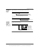
Load Values The following table shows the load values.
Zeros in the 4X registers also mean no change. Setpoint, maximum count and
assert time can only be set to zero using the Modzoom screens. When the registers
in this example are echoed, zeros will appear but the actual content in the module
will be unchanged from previous values. In this example, Counter 2 is disabled and
its outputs and timed assert have not been selected. Registers 400204 - 6 have no
meaning.
After the module executes the Configure and Load Value’s commands, they are
echoed in the I/O mapped 3X registers except for the command register’s low 8 bits.
Command execution time by the module is 1 ms. Actual time between the 4X
register block move and the echo response display in the 3X registers is dependent
on User Logic and hardware configuration. An echo of the Configuration command
registers would appear as follows:
Response for
Configuration
Command
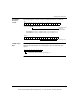
The following table shows the echo response for the configuration command.
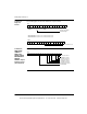
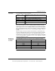
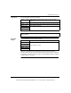
400201 0243 LOAD VALUES command, disable Counter 2, preset and enable
Counter 1
400202 0064 Counter 1 maximum count, count after which Output 1B turns on
400203 0032 Counter 1 setpoint, count when Output 1A turns on
400204 0000 Counter 2 maximum count (not used in this example)
400205 0000 Counter 2 setpoint (not used in this example)
400206 0000 Output Assert Time (Not used in this example, one output only, if
used)
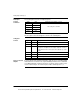
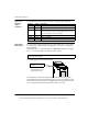
Register Value
300001 0100
300002 0000
300003 3100
300004 0000
300005 0000
300006 0000
This document provided by Barr-Thorp Electric Co., Inc. 800-473-9123 www.barr-thorp.com