
Hardware reference guide


Intelligent/Special Purpose
35013379 02 October 2007 379
Module
Functions
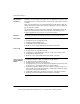
The following functions apply to the EHC202 high speed counter module.
COUNT UP The input counter is reset to zero if the count direction input is UP and a preset
(hardware or software) or Load Value command is sent to the module.
When counting in the UP direction, the input counter increments to the maximum
value, the next input pulse sets the counter to zero and it continues counting back
up to the maximum value.
COUNT DOWN The input counter is set to maximum count if the count direction is down and a preset
(hardware or software) or Load Value command is sent to the module.
When counting in the DOWN direction, the input counter is decremented from the
maximum value to zero. The next pulse resets the input counter to the Maximum
value and the increment down starts again.
REMOVE
ENABLE
This function disables the input counter, causing it to stop incrementing and hold the
count accumulated prior to disabling.
OUTPUTS When configured in the count mode, outputs will turn on for defined times when
setpoints or maximum values have been reached.
No output assertion in two 32 bit counter mode or rate sample.
Programmed ON time for outputs can be set for one channel, one output and one
trigger point only.
In a running controller, latched outputs are turned off only by a hardware RESET
input. If no reset is provided, the outputs latched on will turn off when the controller
is stopped.
COUNTER
PRESET
This is both a hardware and software function. In the event that both methods are
used, the last one executed has precedence. An input counter will be automatically
preset whenever a new maximum value or rate sample time is loaded.
COUNTER
ENABLE
Both hardware and software enables are required for an input counter to operate.
An input counter will be automatically software enabled whenever a new maximum
value is loaded or a preset (hardware or software) is sent to it.
RATE SAMPLE
VALUE
The rate sample value is held and may be accessed during count operations. The
value read is from the last configured and completed rate sample interval.
QUADRATURE
MODE
When the module is configured for quadrature mode operation, the counter requires
encoder pulses on inputs A and B.
In quadrature mode, all input signal edges are counted. A 60 count/revolution
encoder will produce a count of 240 for one shaft rotation.
This document provided by Barr-Thorp Electric Co., Inc. 800-473-9123 www.barr-thorp.com