
Hardware reference guide

Intrinsically Safe Modules
418
35013379 02 October 2007
15.1 Intrinsically Safe Modules - General Information
Intrinsically Safe Modules – General Description
Introduction The following information is specifically concerned with the application of intrinsic
safety with regards to the installation and field wiring of the Quantum Intrinsically
Safe series of modules. It provides a general description of intrinsic safety and how
it is accomplished in Quantum modules, how they should be installed, precautions
that should be observed, and wiring and grounding practices that must be followed.
Intrinsic Safety Intrinsic safety is a technique for ensuring that electrical energy supplied to circuits
in a hazardous area is too low to ignite volatile gases either by spark or thermal
means. Intrinsically safe circuits use energy limiting devices known as intrinsically
safe barriers to prevent excess electrical energy from being applied to electrical
equipment located in the hazardous area.
Module Location The Quantum Intrinsically Safe family of modules are entity certified to be installed
in safe areas to monitor/control intrinsically safe apparatus located In hazardous
areas.
Intrinsically Safe
Barriers
All Quantum Intrinsically Safe modules use galvanic isolation to provide the
intrinsically safe barrier between them and the field devices located in hazardous
areas. Opto-isolators are located within the modules between the field side and the
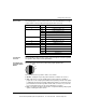
Quantum backplane bus circuitry. The maximum agency specified intrinsically safe
parameters are:
Intrinsically Safe
Power Supply
DC/DC converters in Quantum Intrinsically Safe modules provide intrinsically safe
power to field devices located in hazardous areas. No external field power is
required where these modules are installed.
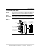
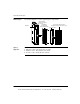
Installation of
Quantum
Intrinsically Safe
Modules
Quantum Intrinsically Safe modules are designed to fit into a standard
140XBPOXX00 Quantum backplane. The modules can be installed in any slot
position in the backplane. (The first slot is normally reserved for the power supply
module.)
V
oc
≤ 28 Vdc and I
sc
≤ 100mA
This document provided by Barr-Thorp Electric Co., Inc. 800-473-9123 www.barr-thorp.com