
Hardware reference guide

Intrinsically Safe Modules
35013379 02 October 2007 421
Intrinsically Safe
Wiring Diagram
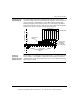
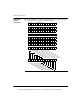
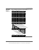
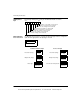
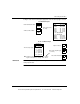
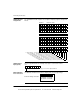
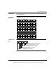
The following diagram illustrates a Quantum Intrinsically Safe module using a
separate raceway to isolate its external wiring to the hazardous area. This is just one
of the possible ways of field wiring the module. Other methods would include
bundling and laying the intrinsically safe wires in the same wiring trough with the
bundled non-intrinsically safe wires, with each bundle tied down and separated by
minimum of two inches of air space through out the wiring runs.
Questions
Regarding
Intrinsically Safe
Wiring Practices
The information concerning intrinsic safety wiring practices, is general in nature and
is not intended to cover installation requirements for any specific site. Questions
regarding intrinsic safety wiring requirements for your site should be referred to the
approval agencies listed.
PS C
P
U
STD
I/O
M
O
D
U
L
E
STD
I/O
M
O
D
U
L
E
I.S.
M
O
D
U
L
E
STD
I/O
M
O
D
U
L
E
BACKPLANE
STANDARD I/O
WIRING
INTRINSICALLY
SAFE WIRING
LABELS
SAFE
WIRING
SAFE
WIRING
H
A
Z
A
R
D
O
U
S
A
R
E
A
S
A
F
E
A
R
E
A
INTRINSICALLY
SAFE WIRING
IN SEPARATE
BLUE RACEWAY
(Intrinsically Safe)
This document provided by Barr-Thorp Electric Co., Inc. 800-473-9123 www.barr-thorp.com