
Hardware reference guide

I/O Modules
35013379 02 October 2007 549
I/O Map Register
Assignment
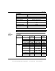
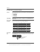
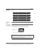
This module requires four contiguous output (4x) registers, which are assigned as
follows .
I/O Map Status
Byte
There is no I/O map status byte associated with this module.
Modsoft Module
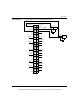
Zoom Selections
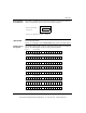
Push <Enter> to display and select the timeout states for each channel. Timeout
state is assumed when system control of the module is stopped.
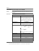
The following figure shows the Channel X timeout state options.
Channel 1 data (0 ... 4,095 +/- 10 V, +/- 5 V, 0 ... 5 V, or 0 ... 10 V)Register 1
Register 2
Register 3
Register 4
Channel 2 data (0 ... 4,095 +/- 10 V, +/- 5 V, 0 ... 5 V, or 0 ... 10 V)
Channel 3 data (0 ... 4,095 +/- 10 V, +/- 5 V, 0 ... 5 V, or 0 ... 10 V)
Channel 4 data (0 ... 4,095 +/- 10 V, +/- 5 V, 0 ... 5 V, or 0 ... 10 V)
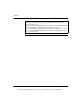
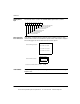
Note: Selecting "Disabled" for any channel causes all others to default to that state.
Output will be what is connected to the module master override terminals, either
common or an external voltage. Output LEDs 1-4 will go out when Disabled is
selected and the module goes to the inactive state.
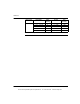
Channel X Timeout State
(per channel)
Channel X User Defined Timeout Value:
0 DEC
Disabled
Last Value
User Defined
This document provided by Barr-Thorp Electric Co., Inc. 800-473-9123 www.barr-thorp.com