
Hardware reference guide

Pwr. & Grnding. Guide
35013379 02 October 2007 793
Grounding
Overview This appendix provides information on grounding issues for the chassis, power
supply Modbus Plus, and other equipment and system requirements.
Chassis
Grounding
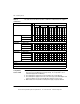
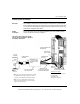
A chassis ground wire is required for each backplane. The wire is connected
between one of four ground screws (located on the backplane) and the main ground
point of the power system. This wire should be green (or green with a yellow stripe)
and the AWG rating must be (at a minimum) sized to meet the fuse rating of the
supply circuit.
Power Supply
Grounding
On each power supply connector there is a ground connection. This connection
must be made for safety reasons. The preferred connection is between the power
supply connector ground terminal and one of the backplane ground screws. This
wire should be green (or green with a yellow stripe) and at a minimum the same
AWG rating as the power connections to the supply.
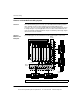
In backplanes with multiple power supplies, each supply should have a ground
connection between its input connector and the backplane ground screws.
Modbus Plus
(MB+)
Communication
Tap Grounding
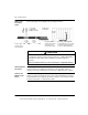
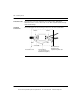
Modbus Plus network drop cables require a ground connection to the backplane.
The connection is made by means of a metal loop clamp that grounds the cable
shield to the ground point. The maximum allowable distance from the ground point
to the drop cable’s connector is 30 cm (11.8 in).
Note: It is recommended that the power supplying the I/O modules be grounded at
the main ground point.
This document provided by Barr-Thorp Electric Co., Inc. 800-473-9123 www.barr-thorp.com